Fence Installation on Challenging Soils: Foundation Mistakes and Solutions
Generic selectors
Exact matches only
Search in title
Search in content
Post Type Selectors

Fence Installation on Challenging Soils: Foundation Mistakes and Solutions

October 23, 2026
2  

Introduction to Geotechnical Conditions and the Problem of Difficult Soils

Designing and constructing reliable fencing structures is a multicomponent engineering task that requires a thorough understanding of geotechnics, structural mechanics, and materials science. In construction practice, there is a false but very common belief that a fence is a relatively light and non-critical structure that does not require detailed geological surveys or complex foundation calculations. However, actual operating conditions prove the opposite: solid fences are constantly subjected to extremely high dynamic wind loads. These aerodynamic forces turn the above-ground part of the fence into a huge sail, and the support pillars into powerful levers that transfer colossal bending moments directly to the foundation. The situation becomes critical if construction is carried out on sites with difficult engineering and geological conditions.

Difficult soils are characterized by structural instability, low bearing capacity, and variability of physical and mechanical properties under the influence of external climatic and hydrological factors. Such bases include peatlands, marshy areas, water-saturated fine and silty sands, as well as heaving loams and clays. For example, peat and marshy layers have an extremely high degree of compressibility, which leads to prolonged and uneven settlement of structures under their own weight. Under the influence of vibrations or a rise in the groundwater level, water-saturated sandy loams can pass into a fluid, quicksand state, completely losing the ability to support any infrastructure elements.

However, the most common and destructive problem in the climatic conditions of most European regions is clayey soils, which are prone to frost heaving. This is a complex thermodynamic process during which moisture retained in the soil capillaries freezes and unevenly expands in volume. Without taking these mechanisms into account, any concrete foundation, even the most massive one, is doomed to the appearance of cracks, distortions, and gradual destruction, which entails the deformation of the metal fence sections and the jamming of entrance groups.

The purpose of this study is a detailed analysis of the mechanisms of interaction of strip, columnar, and combined foundations with difficult soils, the identification of critical errors at the design and construction stages, as well as the consideration of advanced methods of base stabilization, injection waterproofing, and load minimization through the use of high-tech ventilated metal facade systems.

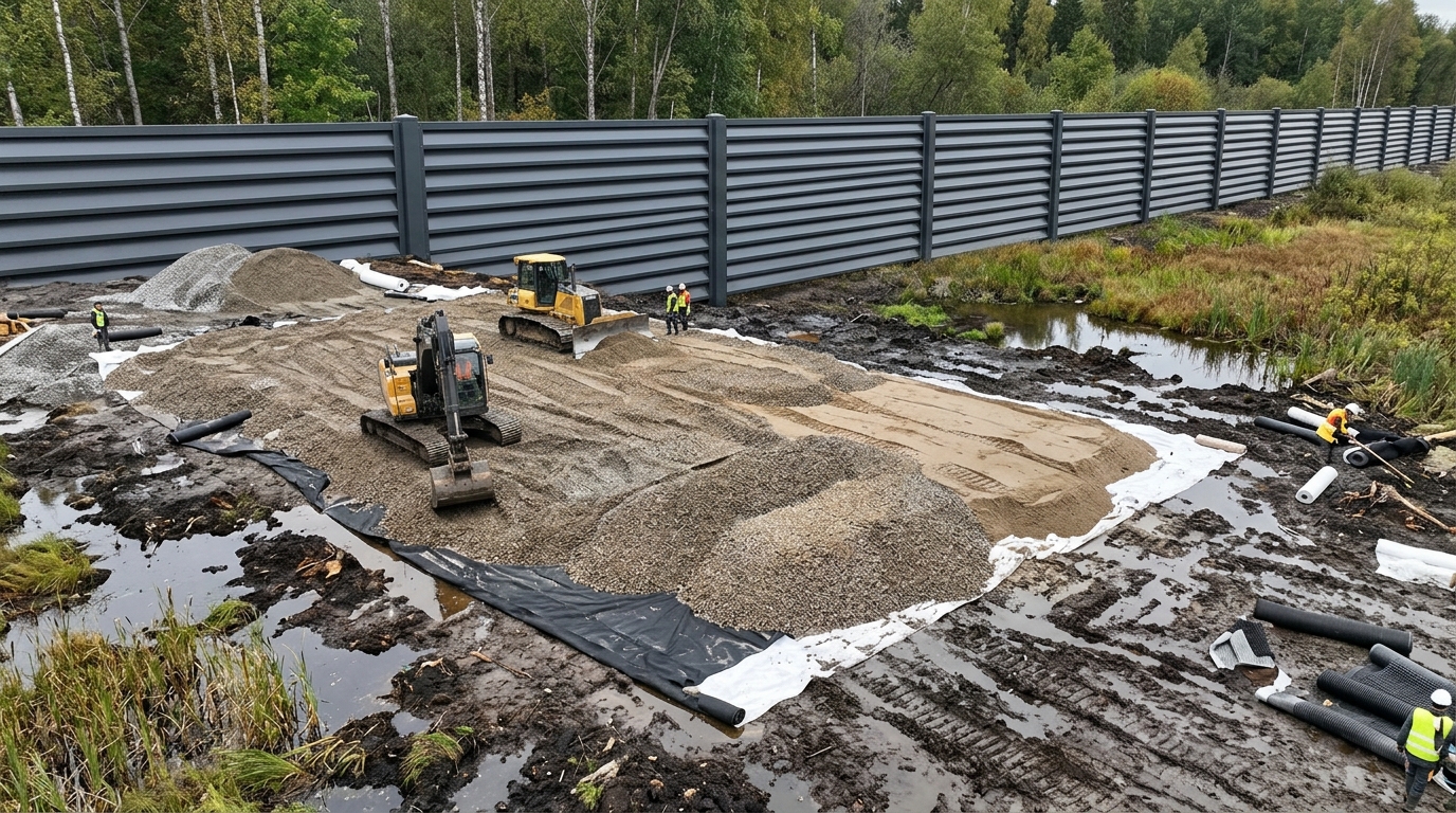
Engineering preparation of marsh… 20261020140731

Physics of Frost Heaving and Normative Indicators of Soil Freezing

The phenomenon of frost heaving is the main destructive geotechnical factor leading to the destruction of the foundations of light and medium structures. The fundamental mechanism of this phenomenon is based on the basic physical property of water to expand by approximately nine percent during the phase transition from a liquid to a solid state. When the ambient temperature drops below the freezing point, the crystallization front slowly descends deep into the soil mass.

In dense clays and loams, water is contained in the form of the thinnest films around soil particles and in capillaries. During freezing, ice lenses are formed, which act like powerful magnets, attracting additional unbound water from deeper, warmer layers due to the capillary effect and the difference in thermodynamic potentials. As a result, the volume of the soil increases continuously throughout the winter period. The pressure generated by ice lenses during expansion is simply colossal: it can reach from two hundred to five hundred tons per square meter. This force repeatedly exceeds the weight of any enclosing structure, even if it is made of monolithic reinforced concrete.

The destructive impact of heaving on the underground part of the fence is realized in two main directions. The first vector is the normal heaving forces that act strictly perpendicular to the base of the foundation, pushing it upwards if the base was laid above the freezing depth. The second vector, which is often forgotten by non-professional builders, is the tangential heaving forces. They occur on the side surfaces of a concrete strip or a support pillar. Freezing wet soil freezes tightly to the porous and rough surface of the concrete. Rising as a result of ice formation, the soil mass acts like a hydraulic jack, pulling the concrete pillar upwards, tearing it from the lower part or pulling it out of the hole. In the spring, when the ice melts, the soil softens and loses its bearing capacity, but the extruded foundation never returns to its original position because loosened earth crumbles under its base. Since these freeze-thaw cycles are continuous and repeat every year, the fence accumulates deformational changes.

To prevent these destructive processes, it is critically important to operate with accurate data on the standard depth of soil freezing in a specific region. According to state building codes (in particular, regulatory documents of the “Bases and Foundations of Structures” series), this indicator is established based on long-term meteorological observations during the coldest periods of the year without taking into account snow cover. Due to their high thermal conductivity and porosity, sandy soils freeze significantly deeper compared to water-saturated clays.

Geographical Region Normative Freezing Depth of Clayey Soils (meters)
Northern and Eastern regions (Luhansk, Kharkiv, Chernihiv regions) 1.0 – 1.4
Central regions (Kyiv, Poltava, Kirovohrad regions) 0.9 – 1.2
Western regions (Lviv, Ternopil, Volyn regions) 0.8 – 1.0
Southern regions (Odesa, Mykolaiv, Kherson regions) 0.7 – 0.9
Carpathian region (Ivano-Frankivsk, Zakarpattia regions) 0.5 – 0.8

Table 1. Averaged indicators of standard soil freezing depth by region based on climatic reference books.

The calculated depth of the foundation laying is determined by engineers by multiplying the standard depth by a special thermal influence coefficient, which takes into account the type of structure and temperature regime. If the sole of the foundation is laid above this mark, the design must mandatorily provide for the complete replacement of the heaving soil with coarse sand or gravel, as well as the arrangement of a drainage system to minimize moisture in the working area.

Fence standing during frost heave 20261020140731

Analysis and Selection of Foundation Structures for Unstable Bases

The strategic choice of the correct configuration of the underground part of the fence is a crucial stage on which not only the durability but also the overall safety of the structure depends. On difficult, heaving, and subsiding soils, the use of a traditional shallow strip foundation (a continuous reinforced concrete strip of shallow depth) is one of the most common and expensive mistakes. A rigid but shallow reinforced concrete frame, laid above the freezing level, is unable to compensate for large-scale uneven movements of soil masses. Under the influence of local heaving, its edges rise, while the central parts can sag, creating enormous internal stresses that lead to concrete rupture.

On the other hand, the simplest columnar (or point) foundation, which involves drilling holes for each support with subsequent concrete pouring, is economically advantageous but has its limitations. If such a pillar is poured into clay soil in the form of a cone expanding upwards (which often happens when the upper part of the hole is expanded with a shovel), it turns into an ideal target for tangential heaving forces. Frosty soil grabs the unevenness of such a “glass” and is guaranteed to push the support out of the ground in one or two winters.

The optimal compromise solution in traditional concreting is a strip-columnar, or hybrid (combined) foundation. This design combines the advantages of deep laying of point supports and reliable rigid fixation of spans using an upper beam. In this architecture, the main vertical load and resistance to wind bending are transmitted to reinforced concrete pillars (piles), which are drilled strictly below the calculated freezing depth. Between these deep supports, a monolithic reinforced concrete grillage (strip) is formed, which unites all the pillars into a single spatial frame, evenly distributing lateral and vertical loads.

A critically important engineering condition for the viability of such a foundation on heaving soils is the creation of a damper compensation gap under the grillage. It is strictly forbidden to pour the strip directly onto the surface of clayey soil. If this is done, winter heaving will lift the grillage with such force that it will be torn from the deeply laid pillars, destroying the reinforcing ties. In practice, either an air gap is formed under the grillage (so-called “hanging grillage”), or, what is more realistic for fences, a thick layer of easily deformable and compressible material is laid — for example, low-density expanded polystyrene or very loose sand, which will absorb the energy of soil expansion.

For proper design, it is necessary to take into account the bearing capacity of various types of soils, since it determines the foundation bearing area.

Soil Type Bearing Capacity of Dense Soil (kg/cm²) Bearing Capacity of Medium Dense Soil (kg/cm²)
Coarse sand 6.0 5.0
Fine sand (wet) 3.0 2.0
Dry clay 6.0 2.5
Plastic clay (wet) 4.0 1.0
Plastic loam 3.0 1.0

Table 2. Calculated base resistance for different soil types. Water-saturated and plastic soils show a critical drop in bearing capacity.

As can be seen from the data presented, moistening clay and loam reduces their strength several times over. That is why in such areas, hybrid systems with deep bearing on stable dry layers are the only reliable option among concrete structures.

Foundation and fence diagram 20261020140731

Screw-Pile and Pile-Grillage Systems as a Standard for Marshy Terrain

Despite the reliability of concrete hybrid systems, there are conditions under which the use of liquid concrete is economically impractical or physically impossible. For marshy massifs, deep peatlands, areas with an extremely high groundwater level, as well as territories with a significant change in elevation (slopes), a screw-pile foundation is the most rational solution.

A screw pile is a high-tech engineering element that consists of a hollow steel tube with a sharp conical tip, to which a wide spiral blade is welded. The geometry of the blade is designed in such a way that during rotation, the pile does not loosen the earth around it, but, on the contrary, cuts it, penetrating deep, and compacts the inter-turn spaces. Thanks to this design, the pile can pass through meters of unstable peat, silt, or liquid sandy loam and securely fix itself in dense, hard bearing rocks (for example, in hard clay or rocky sand), which lie significantly below the freezing or subsidence zone.

In such a foundation, a wide steel blade acts as a dead anchor. It equally effectively prevents both the pressing of the pipe deep under the weight of massive fencing sections and its extrusion under the influence of insurmountable forces of frost heaving. If the solid layer lies too deep, the “hanging pile” principle is used, when the support is held in the ground not by resting on a solid bottom, but due to colossal friction forces between the surface of its trunk, blades, and the surrounding compacted soil.

The installation process of screw piles has undeniable advantages in speed and cleanliness. It does not require digging deep trenches, removing hundreds of cubic meters of excavated soil, and does not destroy the existing landscape or lawns. Installation can be carried out even in winter, through frozen ground. Piles are screwed in manually using long levers or using specialized hydraulic machines on crawler tracks.

After immersing all elements to the design mark, their upper edges are cut off by an angle grinder in a perfectly horizontal line using a laser level. On slopes, the length of the piles can vary significantly, compensating for elevation changes without the need to build expensive stepped concrete plinths. Then comes a critically important stage: the internal cavity of each trimmed pipe is obligatorily filled with a high-grade sand-cement mortar. This is done not only to give the pipe additional mass. Concrete pouring completely displaces oxygen and condensation from the metal cylinder, blocking internal corrosion processes, and, most importantly, multiplies the rigidity of the pile, increasing its resistance to bending wind loads.

The service life of such a foundation depends on the quality of the metal’s anti-corrosion protection. Using cheap primers is a short-sighted decision. Reliable piles are coated with two-component polyurethane or epoxy resins, which create a thick barrier resistant to abrasive friction of stones and the aggressive chemical impact of groundwater.

Construction Expense Item Foundation on Screw Piles Concrete Columnar Foundation
Earthworks (digging/drilling) Not required (no costs) High (depends on hole volume)
Installation works Fast screwing (mechanized) Concreting, waiting for curing
Soil disposal Not required Mandatory soil removal
Seasonality dependence Installation possible all year round Limitations at freezing temperatures

Table 3. Comparative analysis of installation process components and financial efficiency of various foundation types, illustrating cost optimization when choosing pile solutions (based on expert calculations).

Metal heads are welded on top of the screw piles, onto which metal fence posts can be directly mounted, or all piles are united by a steel channel (metal grillage), creating a rigid binding. This is an ideal base for installing light but strong ventilated sections.

Schematic diagram of foundation … 20261020140731

Earthworks: Trench Preparation and Formation of Cushioning Pads

In cases where the choice is made for a concrete strip or combined foundation, the first stage of practical implementation is carrying out accurate earthworks. It is at this stage that systemic errors are made, which become irreversible after pouring the concrete mix. The depth and width of the trench for the strip plinth must not simply correspond to the dimensions of the future concrete, but have a technological margin. The width of the trench should be twenty to thirty centimeters wider than the design width of the strip. This free space is vitally necessary for the reliable installation of wooden or plywood formwork panels with spacers, as well as for the possibility of carrying out further external waterproofing works and drainage arrangement after removing the formwork. On light soils, digging trenches up to fifteen meters long is often done manually, but for long perimeters and dense loams, it is rational to rent compact trenchers or mini-excavators.

One of the most destructive technological mistakes is pouring heavy concrete directly onto the bottom of a newly dug trench consisting of liquid clay, loam, or silty sand. According to geotechnical standards, an artificial base — a cushioning sand-crushed stone pad — must be created under the sole of any monolithic foundation. The thickness of this pad varies from fifteen to thirty centimeters, depending on the degree of heaving of the local soil. This engineering layer performs three critically important functions.

First, it replaces a layer of dangerous, excavation-loosened local heaving soil with a stable, non-heaving material (sand and crushed stone), which does not retain water and, accordingly, does not expand when the temperature drops below zero. Second, the pad acts as a powerful planar drainage, breaking capillary connections and diverting moisture away from the concrete foundation sole, which minimizes the risks of water absorption by concrete. Third, it works as an elastic damper that ensures uniform distribution of massive vertical loads from the fence’s weight over a much larger area of the underlying rock, preventing dangerous local settlements.

However, simply pouring a truckload of sand and crushed stone into a trench is a waste of resources if the use of geotextiles is ignored. Geosynthetic non-woven fabric, made from ultra-strong polypropylene or polyester continuous threads, acts as a spatial separator and filter. Without a geotextile layer, under the constant influence of precipitation, groundwater movements, and micro-movements from the structure’s weight, large and sharp fractions of crushed stone will quickly and irreversibly sink into the soft clay or peat base. Simultaneously, the finest clay particles will rise upwards, completely silting up the clean sand. As a result of this phenomenon, known as suffosion, the sand and crushed stone pad loses its drainage properties, turning into ordinary mud that freezes and heaves.

Purpose of Geotextile Recommended Material Density (g/m²)
Landscaping works, weed protection Up to 150
Separation of layers under light pedestrian paths 150 – 200
Bases for fences, driveways, passenger car parking lots 250 – 300
Main roads, bases for heavy reinforced concrete structures 350 and higher

Table 4. Selection of geotextile fabric density depending on the operational load to prevent the mixing of soil layers.

The correct technological process requires thorough cleaning of the trench bottom from root residues and construction debris. After that, primary leveling and tamping of the soil itself are carried out. Next, the bottom and walls of the trench are lined with high-density geotextile sheets (minimum from two hundred and fifty grams per square meter) with a mandatory overlap of sheet joints by twenty to thirty centimeters. Only into this “synthetic trough” do they begin to pour river or quarry sand and gravel layer by layer. It is critically important that each poured layer up to ten centimeters thick is intensively moistened with water and tamped using a heavy vibratory plate compactor until maximum density is achieved. Flooding sand with water is necessary so that water streams force small grains of sand to fit snugly against each other, filling all voids. Ignoring vibrational compaction will result in the loose sand experiencing rapid and uneven shrinkage under the weight of the reinforced concrete plinth, which is guaranteed to cause fractures and cracks in the already finished fence foundation.

Builders compacting foundation t… 20261020140731

Design and Installation of Spatial Reinforcement Cages

Concrete is a unique building material that demonstrates phenomenal compressive strength indicators, allowing it to withstand the weight of multi-story buildings. However, its resistance to tensile forces is ten to fifteen times lower. The foundation of a massive fence works according to the laws of mechanics as a long continuous beam lying on an elastic, unstable base. Given seasonal soil expansions, uneven heaving, and colossal impacts of wind streams on fence sections, bending moments constantly arise along the entire plane of the structure. Somewhere the soil sags, and the beam bends downward, stretching its lower part. In other places, heaving pushes the foundation edge upward, creating tensile stress in the upper zone of the concrete. Protection of the concrete monolith from brittle fracture during such dynamic bending is provided by steel reinforcement, which has an extremely high tensile strength and takes on all these stresses.

The grossest and most common reinforcement error is the placement of steel rods along the central neutral axis of the foundation strip, or their laying in a single layer. To ensure safety, a full-fledged spatial cage must be formed. This cage consists of two working belts: upper and lower, which absorb tensile forces from both directions. For longitudinal working belts, ribbed reinforcement with a diameter of ten to sixteen millimeters is used. These long rods are united into a single system by smooth transverse and vertical reinforcement (stirrups), which counteracts shear forces.

An extremely important parameter is compliance with the concrete cover layer. The distance from the outermost steel bar to any external plane of the concrete surface must be at least forty millimeters. If the reinforcement is carelessly laid close to the wooden formwork or lies directly on the crushed stone at the bottom of the trench, after removing the panels it will come into contact with atmospheric oxygen and aggressive groundwater. A rapid corrosion process will begin. As it forms, iron hydroxide (rust) significantly increases the metal’s volume. This internal expansion creates such pressure that it forces the outer layers of concrete to chip off, leading to complete exposure of the cage and a catastrophic loss of bearing capacity of the entire foundation.

Engineers pay special and close attention to the reinforcement of structural corners and T-junction locations. Simple crossing of reinforcing bars at corners (overlapping them crosswise) is an absolutely unacceptable mistake. The corner is a geometry of maximum internal stress concentration. If a rigid connection is not provided, under the influence of tensile forces, such a corner will simply tear apart and open, forming a through vertical crack. All longitudinal bars must be anchored (securely connected) using L-shaped or U-shaped bent steel elements. At the same time, the overlap length of the bent element on the straight bar must be at least forty to fifty diameters of the reinforcement used (for a bar with a diameter of ten millimeters, this is a half-meter connection).

In addition, specialists warn against the thoughtless use of welding machines to connect most classes of construction reinforcement. Welding creates rigid, immovable nodes, and the ultra-high temperature of the electric arc changes the metal’s molecular crystal lattice, significantly reducing its plasticity and tensile strength precisely at the point of the welding seam. Correct assembly of a spatial cage must be carried out exclusively by tying knots using soft annealed steel wire or plastic construction ties, which leaves the cage micro-mobility during the pouring and shrinkage of heavy concrete.

Steel reinforcement cage inside … 20261020140731

Concreting Technology and Prevention of Cold Joints

Even a perfectly prepared trench and a flawlessly tied cage can be negated by violations during the concreting process. For a foundation for a permanent fence on difficult soils, state regulations require the use of factory-made heavy concrete of high grades, in particular, class no lower than B20 or B22.5 (which corresponds to the old M300 grade). Such a material has the necessary density to withstand pressure and sufficient resistance to freezing cycles.

One of the most common and most harmful habits of construction crews is adding an uncontrolled amount of water to the mixer directly at the construction site. This is done to make the mortar more liquid and fluid, which significantly facilitates its stretching along the trench with shovels. However, this practice is fatal to the structure’s quality. Factory mortar has a strictly calibrated water-cement ratio necessary for the proper chemical reaction of cement hydration. Excess water added on site does not react. It remains in the bulk of the concrete in the form of microscopic drops and lenses. Over time, this water evaporates, leaving behind millions of empty capillary channels and pores. As a result, the brand strength of the material rapidly drops by twenty to thirty percent, and its frost resistance is reduced almost to zero, since these pores will fill with moisture again in winter and ice will tear the concrete from the inside.

The pouring of the foundation strip must occur continuously, in a single monolithic cycle. If the process is interrupted for a time exceeding the period of initial chemical setting of the cement (usually two to three hours at a temperature of twenty degrees Celsius), a so-called “cold joint” forms at the boundary of the stop. This is a physical parting plane between the old layer that has already begun to crystallize and the new, still liquid layer of concrete. This joint will never have the monolithic strength of the entire strip in the future and is guaranteed to become the weakest link through which moisture will penetrate massively into the structure, and where a fracture will occur at the slightest load. That is why it is necessary to calculate the volume in advance and order truck mixers with such a schedule that they ensure a continuous supply of the mixture.

Immediately after pouring the mortar into the wooden formwork, it must compulsorily undergo mechanical processing using deep vibrators. High-frequency vibration turns the thick concrete mix into a fluid thixotropic mass. This forces air bubbles, which always form during mixing and dropping of the mixture, to rise to the surface and escape, and the mortar itself to tightly wrap every steel rebar. Categorical refusal of vibro-compaction leads to the formation of significant shells, voids, and caverns in the concrete bulk. Air pockets around the reinforcement prevent steel adhesion to concrete, causing a general catastrophic weakening of the bearing pillars and fence strip.

After successful pouring, the concrete requires careful maintenance, especially during the first two weeks of the strength gain process. At this stage, the worst thing that can happen is the rapid drying of the surface under the sun’s rays. Moisture loss stops hydration, as a result of which the surface is covered with a network of deep shrinkage cracks, and strength drops by half. To prevent this, the newly poured foundation must be covered with plastic wrap to create a greenhouse effect and intensively watered with water several times a day during the first week.

Workers pouring concrete for fence 20261020140731

Engineering Moisture Diversion Systems: Drainage and Blind Area Installation

Water is the root cause of the absolute majority of destructive processes in soils and building materials. Regardless of how well the concrete was poured or what thickness of reinforcement was used, constant and prolonged contact of the foundation with moisture will slowly but inevitably destroy its internal structure. Capillary suction of salts dissolved in water contributes to concrete leaching and corrosion of internal reinforcement, and constant wetting of the adjacent soil triggers frost heaving mechanisms deadly to the structure. To provide comprehensive and durable protection for the fence base, engineers implement two independent security contours: diversion of underground groundwater and isolation of the structure from surface precipitation.

Deep perimeter drainage around the fence is strongly recommended on sites with complex terrain, a high underground water level, and on slopes where there is a high probability of accumulation and shifting of water-saturated soil masses. The classic scheme of wall-adjacent ring drainage involves laying a narrow trench parallel to the foundation. The most important parameter here is maintaining a stable gravitational slope of the pipe from one to two centimeters for every meter of the main line’s length.

The drainage main installation technology conceptually resembles the creation of a protective pad. The bottom of the drainage trench is formed with sand to set the slope angle, lined with a continuous sheet of filtering geotextile, and covered with a thick layer of clean, washed gravel. A special corrugated perforated polymer pipe is laid on this pad. After that, the geotextile is wrapped over the crushed stone casing with an overlap, forming an airtight closed filter channel. This system freely allows purified water into the pipe through micro-holes but reliably retains the smallest particles of silt and clay, preventing the system from silting up. The underground moisture collected in the pipe is directed by gravity to collection inspection wells or safely diverted far beyond the residential plot into natural reservoirs. On large and flat territories, it is advisable to use a “herringbone” pattern, where the main trunk collects water from many branched side branches.

The second, equally critical protection element is the installation of a blind area (apron). This is a waterproof architectural strip closely encircling the concrete fence plinth at ground level. The main mission of the blind area is to intercept rain and meltwater flowing from walls or roofs and throw it as far away from the foundation wall as possible, preventing its direct penetration into the construction-loosened soil directly at the structure’s base. According to engineering recommendations, the width of such a protective strip should be from seventy centimeters to one and a half meters. On heaving clay soils, the blind area must imperatively be wider to guarantee coverage of the active soil shedding and wetting zone.

There are several structural varieties of blind areas:

  1. Rigid blind area is made of monolithic reinforced concrete or asphalt. It provides the highest strength but is vulnerable to cracks during soil movements.
  2. Semi-rigid blind area is created from shaped paving elements (clinker bricks, paving slabs) laid on a waterproof base and sand cushion. It provides an excellent aesthetic appearance and partial elasticity.
  3. Soft blind area is made from a carefully tamped layer of water-resistant fat clay (so-called “clay lock”), on top of which a layer of decorative gravel is poured to protect against washing away.
  4. Hidden blind area is the most modern landscape design solution. Under a fertile layer of soil with a lawn, a waterproofing membrane with crushed stone is laid, which diverts water into the drainage invisibly to the eyes.

The main and inviolable engineering rule when creating any type of blind area is strict adherence to a slope from the plinth plane at the level of two to three percent (that is, the plane must drop two to three centimeters for every meter of its width). The absence of a slope angle or, even worse, a reverse slope towards the wall is a catastrophic mistake. In this case, the blind area turns into a dangerous water collector, which concentrates huge flows of water and directs them right under the foundation sole, accelerating its destruction.

Also, between the vertical concrete fence plinth and the blind area plane, an expansion (compensation) joint must be obligatorily left and formed. Since the massive deep fence foundation and the thin, surface blind area have entirely different masses, bearing areas, and temperature regimes, they will respond to seasonal changes and soil movements with different amplitudes. If these two elements are rigidly tied with concrete or metal, uncontrollable ruptures and cracks will inevitably occur at their junction due to the stress difference. This expansion gap is usually filled with an elastic polyurethane tubular sealant and filled with a bituminous mastic that preserves full system tightness during mutual thermal and physical displacements of elements.

Drainage system around metal fence 20261020140731

Modern Methods of Stabilization and Repair of Deformed Foundations

If critical mistakes during foundation design and construction were already made by builders, and the fence began to show obvious signs of an emergency state — deep through, diagonal, or vertical cracks appeared in the concrete plinth, a dangerous deviation of support pillars from true vertical is observed, and the entrance gate door or heavy leaves of automatic gates began to jam in their frames — it is necessary to immediately move to a professional stage of diagnostics and structural rescue.

Plaster beacons are used for the primary diagnosis of crack behavior. A strip of brittle plaster with a date mark is applied across the cleaned crack. If the plaster tears after a few weeks, this indicates that the foundation continues its active movement, and the problem lies in soil base instability, rather than just surface concrete shrinkage. Traditional, classic repair of emergency bases involves extremely large-scale earthworks: deep excavation of wide trenches around damaged areas, creation of additional reinforced retaining concrete belts, and complex pouring of fresh mortar under the existing deformed sole. This archaic process is extremely long, expensive, and dirty. Moreover, it completely destroys landscaping, expensive lawns, and irrigation systems on the site. It can also be fatally dangerous to the structure itself, as sudden removal of retaining soil around a deformed foundation can provoke its instant and complete collapse under its own weight.

At the current stage of engineering geotechnics development, the most rational, fastest, and safest method of saving emergency foundations is injection technology (resinification or geopolymer soil stabilization). The essence of this revolutionary technique lies in injecting two-component innovative polyurethane, acrylic, or epoxy resins directly into the internal concrete body or directly into the base soil under extremely high pressure.

To restore the monolithicity of a deeply cracked concrete grillage, the force injection gluing method is used. Along the open crack line, at a calculated angle of forty-five degrees to the surface plane, small-diameter holes are drilled. These holes intersect the fracture plane deep in the concrete mass. Special metal injectors (packers) are screwed and tightly fixed into these channels, equipped with reliable check valves resembling tire valves. Using powerful electric piston or diaphragm pumps, liquid low-viscosity epoxy or polyurethane hydroactive resin is pumped into the packers under pressure of one hundred to four hundred bar. The material quickly and completely fills the smallest capillaries and hidden voids inside the concrete strip, literally squeezing out accumulated water from there (some polyurethane resins harden upon contact with water in less than a minute). After final polymerization and resin curing, the crack turns into a monolithic hermetic seam. This polymer bond often exceeds the physical indicators of intact concrete itself in terms of tensile strength, stopping further expansion of the fracture.

When the cause of a fence tilt is weakening, subsidence, or underground water washing out the sand cushion under the foundation sole, the method of deep base compaction with geopolymers is applied. Vertical through-holes are drilled through the concrete foundation body or closely adjacent to it, reaching weak, water-saturated, or decompaction soil layers. Special polyurethane composites are pumped down through these channels. While mixing the two components, they enter a vigorous chemical reaction accompanied by intensive gas release and rapid material volume expansion tens of times over.

Expanding in a confined underground space, the geopolymer creates enormous internal pressure that presses and pushes away surrounding weak soil, completely fills water-washed underground caverns, and forms a new, ultra-strong, and lightweight bearing pad under the concrete foundation. The greatest advantage of this method is its surgical precision: by changing the pressure and feed rate of the expanding polymer, engineers can, millimeter by millimeter, control the lifting of a sunken foundation section, restoring perfect verticality to fence pillars and operability to gates without any excavation of earth.

An additional innovative method of foundation preservation is the seamless spraying of rigid polyurethane foam onto the outer surface of an excavated plinth. Thanks to its closed-cell structure, this synthetic material has no joints and creates a continuous monolithic barrier. It performs a dual function: it serves as perfect and absolute waterproofing with near-zero water absorption, and acts as a highly effective space-grade thermal insulator. Insulation of the foundation and its adjacent blind area makes it possible to artificially reduce or entirely eliminate soil freezing depth in the fence base zone. The earth under the insulated area remains warm in winter due to the conservation of deep-layer geothermal energy. This completely rules out the soil water crystallization process and, as a result, forever neutralizes the destructive forces of frost heaving, saving the structure from seasonal deformations.

Engineer repairing fence foundation 20261020140731

Load Reduction Using Aerodynamic Enclosing Structures

Any, even the most expensive and advanced geotechnical measures to strengthen the underground foundation may prove insufficient or ineffective if the above-ground part of the fence generates excessive and unjustified loads on the system. Traditional, widespread, but physically and morally obsolete solutions include high fences made of solid metal corrugated board, polycarbonate panels, or solid massive brickwork. The main and most critical problem with solid metal or polymer planes is their absolute aerodynamic impermeability, which creates the notorious giant sail effect.

When powerful gusts of autumn or spring winds hit such a solid obstacle, the colossal kinetic energy of air masses turns into destructive bending forces. Through metal support pillars, these forces act as a huge lever directly on the concrete grillage, literally trying to turn the heavy foundation inside out of the ground, loosen piles, or break the concrete strip in its weakest points. Aside from the destructive impact on the foundation, blind fences completely block the natural circulation of air on the site, creating a negative “greenhouse effect” that harms plants and trees near the fence.

For a radical neutralization of this negative factor, but without any loss of privacy and territory security, modern building science and architectural design propose the use of metal ventilated louver-type fences. Products from advanced manufacturers, such as “Mehbud”, are designed based on profound knowledge of aerodynamic stream dispersion. Thanks to an intelligent system of individual profiled metal slats located at a specific calculated angle or with special technological gaps, the kinetic energy of even a strong wind is effectively split into smaller streams. These streams pass freely through the fence, completely losing their destructive power. Such a solution allows reducing peak bending loads on the underground foundation part by several times compared to blind fences. This, in turn, allows architects to significantly optimize costs for large-scale earthworks, reinforcement, and volumes of heavy concrete, making the overall structure safe, stable, and economically viable even on the most difficult clay slopes or weak soils.

Among the assortment of modern lamellar structures, several flagship modifications stand out, capable of solving the most complex architectural and engineering tasks:

Premium segment fences like “Blinds“ (presented in special variants Classic, Premium, Exclusive, Lego) involve placing Z-shaped or V-shaped metal slats at a carefully calculated angle. They form inclined air channels that freely and silently transmit wind and partially scattered soft sunlight. However, thanks to the tilt angle, they visually completely block the direct view of the site from the street, preserving one hundred percent privacy of the residents. The use of durable galvanized steel with a multi-layer polymer and polyester coating makes these systems totally immune to rust, corrosion, and aggressive ultraviolet radiation.

For spacious sites, minimalism or barnhouse style territories, where wind impacts in open areas can reach storm values, ventilated “Rancho“ systems fit perfectly. These are wide horizontal profiled slats mounted on load-bearing pillars with small, symmetrical gaps. The two-sided placement of Rancho slats guarantees incredibly high torsional and bending metal stiffness, making each section virtually monolithic in its resistance to physical deformations and impacts. Wide Rancho modifications or “Brus“ fences, thanks to the use of significantly enlarged cross-section elements, allow forming surprisingly strong, massive, but visually light spans that, using special coatings, perfectly repeat the complex texture of natural wood, exceeding it in strength dozens of times.

In those exceptional cases when the client or project requires completely solid protection without any gaps for light, the plant offers the engineering system “Horizont“. Thanks to special lock joints along the entire length, massive profiled strips are connected to each other, forming a blind solid metal canvas. However, unlike cheap corrugated sheets, due to the presence of deep horizontal stiffening ribs on each slat, this system maintains flawless structural integrity, does not vibrate, and does not produce a roar under hurricane wind pressure, preserving the integrity of attachments to pillars.

Separately, a revolutionary approach to installation speed should be noted: the ability to purchase fences in the format of ready-made kits (sets). This principle allows receiving a full set of perfectly fitted standard-size elements, reducing installation time from several weeks to a few days and not requiring the involvement of heavy specialized equipment or welding machines on site. The integration of such high-tech, well-thought-out above-ground systems in combination with properly and deeply designed screw-pile or reinforced grillage foundations creates a flawless and reliable engineering symbiosis. Such an integrated approach guarantees that the fence will maintain its strict geometry, flawless aesthetics, and protective functionality for decades, absolutely independent of the most challenging geological or climatic tests.


Engineering preparation of marsh… 20261020140731 2

Conclusions and Expert Recommendations

An in-depth technical analysis of the problems of building massive fencing structures on unstable, heaving, sandy, and marshy soils categorically proves that a fence foundation is a complex and full-fledged engineering structure. Any amateurish attempts to save finances at the stages of preliminary geological design, using inappropriate shallow strip designs without analyzing the normative soil freezing depth, or blatantly ignoring strict reinforcement and water drainage norms are guaranteed to lead to fatal destruction, the correction of which requires disproportionately large financial expenses and site damage.

The fundamental and unshakable rules of successful fence installation lie in choosing the most reliable base. On swamps and slopes, these are screw-pile systems; on clayey soils — combined pile-grillage systems with mandatory damper compensation gaps. It is important to observe the technology of preparing a cushioning pad with obligatory separation of layers by durable geotextile, as well as the implementation of spatial two-belt reinforcement of the concrete strip with corner reinforcement by L-shaped anchors instead of forbidden welding.

Critically important for the life of concrete remain measures for managing capillary and atmospheric soil moisture — the installation of circular drainage lines and proper blind areas with an accurate slope away from the wall. In case of emergency situations, the application of advanced methods of polyurethane resin injection and geopolymer lifting allows saving already existing structures without dirty dismantling works, forever stabilizing the structure’s geometry. Finally, the correct choice of the metal fence type in favor of aerodynamic ventilated louver-type systems can drastically reduce operational wind loads on the underground part, creating a monolithic, durable, and reliable barrier around a private or commercial territory for decades.

author
Alex Z
About the author:

Oleksandr — Digital Marketing Expert for Construction & Manufacturing Industries Oleksandr is a seasoned digital marketing specialist, delivering powerful results for the construction and manuf...

More
0 0 votes
Article Rating
Subscribe
Notify of
guest
0 Comments
Oldest
Newest Most Voted