From Concept to Code: Digital Resources for Sheet Metal Bending and Profiling
This section provides the practical tools and knowledge required to translate a design concept into a manufacturable sheet metal part. Bridging the gap between architectural vision and fabrication reality requires an understanding of the software, the physical limitations of the material, and the data format needed for a seamless handoff to the fabricator.
The Digital Workbench: Specialized Sheet Metal Software
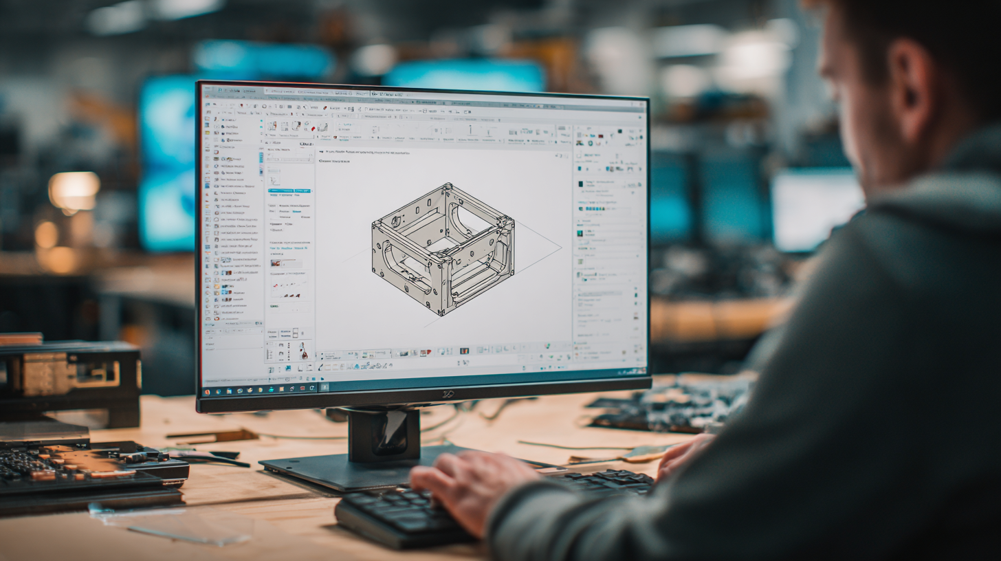
While many 3D modeling programs can create the form of a metal component, specialized sheet metal design software understands the process. The premier tool in this category is Autodesk Inventor, which features a dedicated sheet metal environment. This environment allows designers to:
- Create Sheet Metal Features: Build parts using commands specific to fabrication, such as creating base faces, flanges, hems, folds, and contour rolls.
- Define Sheet Metal Rules: Establish critical parameters like material thickness, bend radius, corner reliefs, and the material-specific K-factor. These rules govern how the software calculates the geometry of the flattened part.
- Generate Flat Patterns: This is the most crucial function. With a single command, Inventor can “unfold” the 3D model into an accurate 2D flat pattern, which is the essential output required for laser cutting or punching before bending.
Autodesk Fusion offers a similar integrated CAD/CAM platform, combining sheet metal design with the ability to generate toolpaths for manufacturing machinery directly within the same software.
Essential Design Guides for Precision Bending
Designing for manufacturability is paramount to controlling costs and achieving high-quality results. The following principles, synthesized from multiple fabrication design guides, should be considered fundamental rules for any sheet metal project.
- Uniform Thickness: A part is made from a single piece of sheet metal, so its thickness must be uniform throughout. Designing with multiple thicknesses in a single component is not feasible.
- Bend Radius: Every bend has an inside radius. Attempting to create a perfectly sharp 90-degree corner will cause the material to crack or deform. A common rule of thumb is to design with an inside bend radius at least equal to the material thickness. Thicker materials require a larger bend radius.
- K-Factor, Bend Allowance, and Bend Deduction: These three interrelated terms are critical for calculating the exact length of the flat pattern.
- K-Factor: A ratio that represents the location of the neutral axis—the plane within the metal that neither compresses nor stretches during bending. Its value typically ranges from 0.33 to 0.50 and depends on the material, thickness, and bending method.
- Bend Allowance: The arc length of the bend along the neutral axis. This is the amount of material that must be added to the sum of the flange lengths to determine the total flat pattern length.
- Bend Deduction: The amount of material that must be subtracted from the total length of the outside flange dimensions to arrive at the correct flat pattern length. It accounts for the material stretching during the bend.
- Flange Length: The length of a flange (the portion of metal after a bend) must be sufficient to be securely held in the press brake tooling. The rule of thumb is a minimum flange length of at least four times the material thickness.
Online Calculators: Quick Verification Tools
For designers without access to advanced CAD software or for those needing a quick feasibility check, several free online calculators are invaluable. Platforms like SendCutSend, Omni Calculator, and Gasparini offer tools to calculate bend allowance and bend deduction. These calculators allow for rapid “what-if” scenarios, enabling a designer to input material type, thickness, bend angle, and inside radius to instantly see if their proposed geometry is viable and to obtain the necessary data for creating a flat pattern.
Preparing for Fabrication: DXF File Best Practices
The final step in the digital design process is exporting the flat pattern for the fabricator. The industry-standard file format for 2D laser and waterjet cutting is the DXF (Drawing Exchange Format). A clean, machine-ready DXF file is essential for a smooth and accurate production process.
Checklist for a Fabrication-Ready DXF File:
- Scale: The drawing must be at a 1:1 scale.
- Convert Text: All text elements must be converted to outlines or paths, as machines cannot read font files.
- Clean Geometry: Ensure all shapes are closed contours. There should be no open gaps, overlapping lines, or intersecting paths.
- Remove Extraneous Information: The file should contain only the cut lines for the part. Remove all dimensions, title blocks, notes, and borders.
- Consider Nesting: For multiple parts, arrange them efficiently on a standard sheet size (a process called “nesting”) to minimize material waste and reduce cutting time and cost.


