The rapid development of augmented reality (AR) technologies and mobile spatial scanning, known in the industry as reality capture, has radically transformed approaches to architectural and construction measurements. Tasks that previously required the use of laser tape measures, optical total stations, scaffolding erection, and significant time investment, today can be performed using a mobile smartphone or tablet with millimeter accuracy. This transition is particularly relevant when designing, ordering, and installing high-tech construction materials. In this context, the products of the Mehbud plant are indicative, which include premium metal fences, innovative facade systems, and complex suspended ceilings that require perfect accuracy at the measurement stage.
For such architectural products manufactured from high-quality galvanized steel, aluminum, or aluzinc with a polymer coating, the accuracy of the initial data is a critical success factor. Any error at the measurement stage inevitably leads to an increase in the material waste coefficient, known as the material waste factor. At best, this turns into financial losses due to ordering extra square meters; at worst, incorrect docking of lamellas, facade cassettes, or ceiling elements, which requires manual trimming on site, damaging the protective polymer coating and provoking corrosion. The use of mobile scanning apps allows negating the human factor, generating accurate 3D models or point clouds (point cloud), from which the areas, heights, and lengths of complex polygons are automatically extracted. This report offers an in-depth analysis of the tools, algorithms, and physical limitations of mobile spatial scanning for measuring areas of facades, ceilings, and fences.
Technological Foundation: LiDAR, ARKit, and ARCore
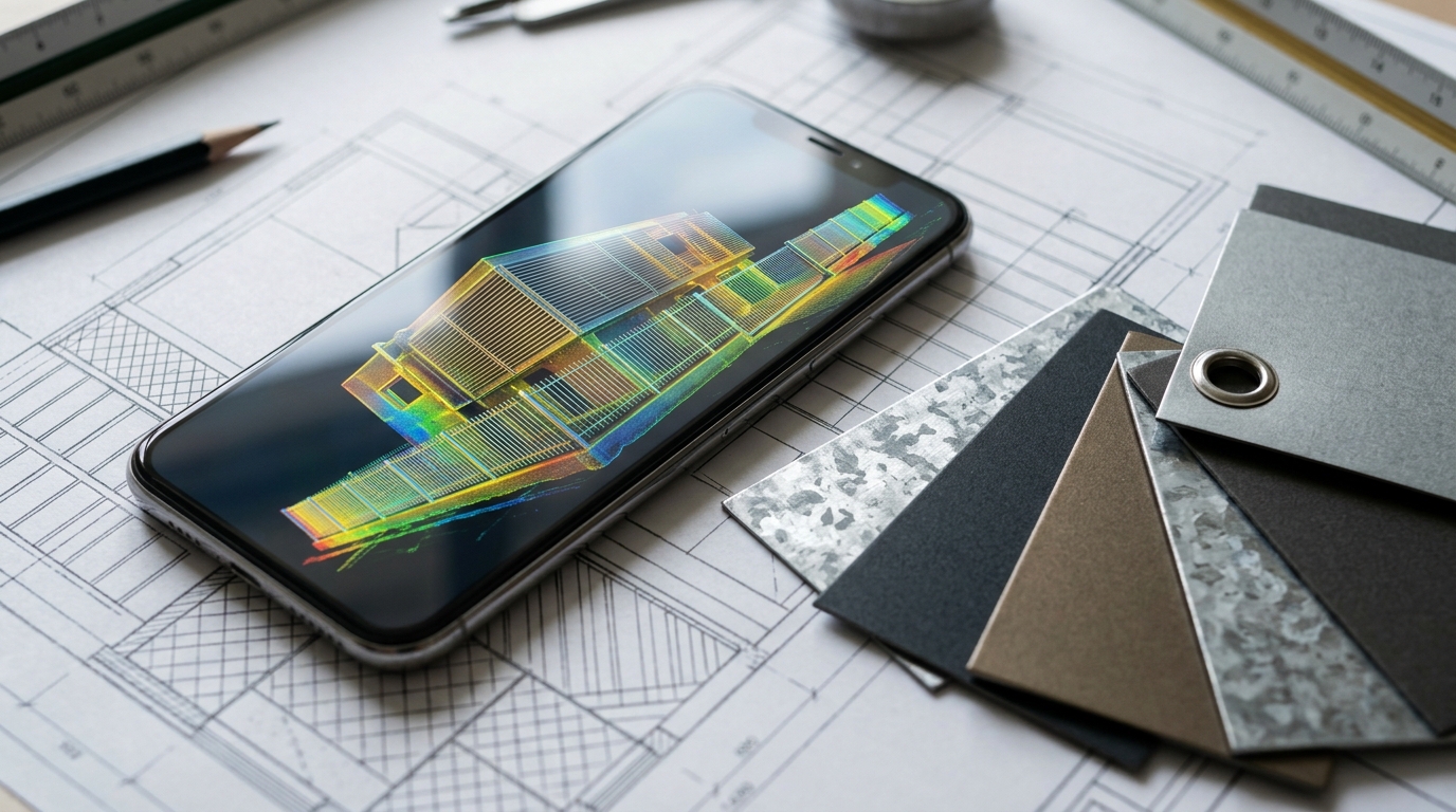
The basis for the effectiveness of modern mobile measurement apps is an unprecedented symbiosis of hardware sensors and software machine vision algorithms. The main role in ensuring industrial accuracy is played by LiDAR (Light Detection and Ranging) technology, which is integrated into professional segment mobile devices (specifically, the iPhone Pro and iPad Pro series). This sensor operates on the time of flight (ToF) principle – it generates a grid of infrared laser pulses, sends them into space, and records the exact time of their return after reflecting off a physical surface. Unlike conventional optical cameras, which rely on contrast and lighting, LiDAR creates a dense point cloud, forming an accurate 3D map of space with minimal errors, making it indispensable for engineering tasks.
At the software level, the mobile spatial scanning ecosystem relies on two dominant frameworks: ARKit for the iOS platform and ARCore for Android devices. Although both systems share a common goal, their architecture and accuracy differ significantly. The ARKit framework, especially in combination with a hardware LiDAR scanner, provides extremely stable motion tracking and fast plane detection. The system is able to instantly identify not only horizontal surfaces (floors, slabs) but also vertical walls, which is critically important when scanning long sections of fences (for example, “Horizont” or “Rancho” models) or large areas of commercial facades. Thanks to LiDAR, ARKit successfully overcomes the problem of positioning error accumulation, known as drift, which usually occurs during prolonged scanning of objects of great length.
On the other hand, ARCore on Android devices primarily uses Visual Inertial Odometry (VIO) algorithms. This method analyzes the displacement of visual feature points across a series of images from the camera, synchronizing this data with the built-in gyroscope and accelerometer readings. ARCore demonstrates excellent results in well-lit environments with textured surfaces, however, it is much more vulnerable to optical illusions. On monotonous planes — such as a perfectly smooth metal facade without visible joints — ARCore may lose spatial tracking because the algorithm lacks visual cues for depth perception.
| Algorithm / Sensor Characteristic | ARKit Platform (with LiDAR) | ARCore Platform (Camera-based VIO) |
| Operating Principle | Direct depth measurement with laser pulses (Time of Flight) and optical tracking. | Analysis of visual contrast feature points displacement and inertial data. |
| Plane Detection | Instant, accurate for horizontal, vertical, and sloped surfaces. | Depends on texture; slower on monotonous metal surfaces. |
| Lighting Resistance | High (works even in twilight thanks to active infrared illumination). | Low (requires uniform bright lighting to recognize textures). |
| Drift Accumulation | Minimal (~1-3 cm per 10 meters), suitable for scanning large facades and long fences. | Moderate to high (can reach 5-10 cm per 10 meters), requires additional verification. |
| Glossy Surface Handling | Phantom laser reflections possible, but overall geometry is stabilized by optics. | Complete loss of tracking possible due to shifting glares during camera movement. |
Understanding these technological nuances is a key stage of work planning. For measuring large facade areas or long lines of fences, where millimeter precision is required to order expensive metal structures from the Mehbud plant, LiDAR devices are the undisputed leaders. They allow engineers to obtain data directly integrated into CAD systems. Mobile apps relying exclusively on the camera should be used for creating preliminary sketches or rough area calculations, obligatorily verifying critical nodes with traditional methods.
Analysis of Leading Spatial Scanning Apps
The modern software market offers a wide range of mobile applications for architects, surveyors, builders, and even private clients. The choice of the optimal tool depends on the ultimate goal: whether the engineer needs a simple area figure for a quick estimate, or a highly detailed 3D model to create a facade elevation and integrate it into a BIM (Building Information Modeling) environment.
One of the most powerful and popular tools for creating 3D models is the Polycam app. It maximally utilizes the hardware LiDAR, generating a textured 3D mesh in real-time. In Space Mode, the operator slowly walks around the building, fence, or room, and the app forms dense geometry right before their eyes. A unique advantage of Polycam is the ability to export the acquired data in professional formats such as DXF, OBJ, or LAS, allowing the object to be instantly transferred into AutoCAD, Revit, or SketchUp. This is the ideal scenario for calculating Mehbud facade systems. The architect can import the facade point cloud, extract the dimensions of window openings, balconies, and door groups with perfect precision to correctly calculate the amount of facade cassettes and load-bearing profiles of the subsystem, eliminating human error.
Another approach is offered by the Magicplan app, which focuses on creating fast and structured 2D and 3D floor plans. Magicplan’s algorithms automatically recognize room corners, walls, door, and window openings. Of special value for facade and ceiling system installers is the Elevation view mode. This tool allows working with vertical planes, accurately marking height elevations. It is indispensable for designing cubic shaped or rack ceilings in complex interiors, as the app automatically generates PDF reports that clearly delineate the floor area, ceiling area, total wall perimeter, and heights.
For the Android ecosystem, which is mostly devoid of LiDAR sensors (except for specialized industrial tablets), developers have adapted ARCore algorithms. The AR Plan 3D and AR Ruler apps by Grymala studio are prime representatives of this segment. Their functionality is tailored towards a classic virtual tape measure, but with expanded mathematical capabilities for calculating area, perimeter, and volume. Extremely useful is the Polyline mode. The user sequentially “pins” virtual points at each bend of the fence, and the app independently calculates the total length of the curved perimeter and forms the infill area. However, engineers must bear in mind that the accuracy of VIO algorithms on Android requires stable lighting and slow camera movement to prevent spatial orientation loss.
It is also worth noting hybrid tools, such as CamToPlan, which allow projecting measurement lines directly onto the video feed. Thanks to the visualization of a “tape” laid out in augmented reality, the operator can evaluate uneven roof contours when installing parapet fences or complex polygons where metal facades meet the ground.
| Mobile App Name | Core Technology | Optimal Use Case | Export Formats | Suitability Level for Mehbud Metal Products |
| Polycam | LiDAR + Photogrammetry | Creating high-precision 3D models of facades and complex fences, export to CAD systems. | DXF, OBJ, LAS, PLY, IFC | High (ideal for precise cutting of facade cassettes and material calculation). |
| Magicplan | LiDAR + ARKit/ARCore | Building wall elevations (Elevation view), planning suspended ceilings, accurate opening determination. | PDF, DXF, XLS, 3D | High (generating automatic estimates for installers). |
| AR Plan 3D | ARKit / ARCore | Fast calculation of wall polygon areas, multi-segment fence line measurements (Polyline). | PDF, JPG | Medium (requires attentiveness on monotonous textures due to optical tracking). |
| CamToPlan | Visual Odometry (AR) | Measuring areas of non-standard surfaces and broken perimeter lines on the terrain. | PDF, PNG, DXF | Medium (excellent for quick terrain measurements, but may suffer from drift). |

Facade Measurement: Cassette, Rack, and Blinds Systems
The Mehbud plant’s assortment for architectural building cladding is extremely diverse and technically complex. It includes large-scale cassette facades (where the width of an individual cassette can vary from 150 mm to 525 mm, and the length can reach up to 12 meters), elegant rack and panel facades, cubic shaped systems, as well as exclusive “Blinds” type facade solutions.
A feature of applying metal facades is a zero-tolerance policy for dimension errors. Most facade panels and cassettes are manufactured at the factory according to individual drawings for a specific object. If the facade area or window layout is measured incorrectly, fitting the material on the construction site is practically impossible without a loss of quality. Cutting galvanized steel with angle grinders damages the protective polymer coating, burns out the zinc layer, and inevitably leads to premature metal corrosion. Therefore, precise calculation is an imperative.
Measuring exterior facades using mobile reality capture faces fundamental hardware physical limitations. The effective range of the built-in LiDAR in modern smartphones and tablets is limited to approximately five meters. This means an engineer can scan a ground floor, entrance group, or a single-story private house with perfect accuracy. However, when trying to capture a multi-story commercial building, the infrared pulses simply scatter in the atmosphere and do not return to the detector. In such cases, professional apps, specifically Polycam, feature an intelligent photogrammetry fallback function — they automatically switch from LiDAR mode to classic photogrammetry, reconstructing upper-floor geometry based on the overlap of a series of photographs.
To ensure maximum accuracy when scanning facades for Mehbud systems, engineers must follow a strict protocol:
First, optimal lighting is critical. Counterintuitively, exterior scanning is best done in cloudy weather with diffuse light, or when the facade is in the shade. Direct sunlight contains intense infrared radiation that can “blind” the LiDAR sensor, negating the pulses reflected from the facade, leading to geometry loss and holes in the point cloud.
Second, the operator’s movement kinematics. For SLAM (Simultaneous Localization and Mapping) algorithms to work correctly, the operator must move parallel to the facade at a constant distance of two to three meters. The camera should be held at such an angle that both the facade itself and the transition line between the wall and the ground fall into the lens simultaneously. This provides the system with a continuous reference plane, stabilizing the spatial model and preventing the distortion of straight lines.
Third, the deduction of window and door openings. When designing Mehbud ventilated facades (especially rack ones), the total wall area is not the final figure for the order. It is necessary to calculate the net area of coverage by subtracting windows, doors, and showcases, and also accounting for the running meters of finishing elements (slopes, flashings, corner trims). Mobile apps allow you to capture the wall entirely and then, in edit mode, select the opening polygons, instantly obtaining the exact area of the metal itself.
Additionally, the specifics of installing ventilated facades must be considered. The resulting 3D model or area reflects the existing wall (concrete, brick, aerated concrete). However, cassette, cubic shaped, or rack facades are attached to a load-bearing subsystem (brackets, crossbars) that stands off from the wall by the thickness of the insulation and the ventilation gap. Due to this geometric offset, the final area of the outer metal facade plane will be larger than the area of the load-bearing wall (especially at the building’s corner sections). This scale factor is obligatorily included in the estimate by the architect after exporting the model to CAD.
Perimeter Unfolding: Area Measurement for Metal Fences
The metal fences sector is one of the most technological directions of the Mehbud plant. The product line covers both completely solid structures (“Horizont”, “Brus”, “Vertical” series) and complex ventilated systems (various modifications of “Blinds”, “Rancho”, the innovative “El Rancho”, and the premium “Blinds Exclusive Lego”). The engineering complexity of these structures lies in the fact that they are prefabricated. They are assembled from individual metal lamellas (steel thickness from 0.45 mm to 1 mm) that integrate into metal U-shaped guides fixed to support pillars (metal, brick, or concrete).
Scanning a site to order a fence is a non-trivial task due to its significant linear length and the impact of the terrain topography. Simple tape measures cannot adequately assess soil elevation changes. Here, apps like AR Ruler, GMeasure AR, or specialized tools like Moasure come to the rescue.
The digitization process of measurements for fences includes several critical stages:
1. Topographic analysis and elevation change calculation: For the correct installation of metal sections, it is important to know the exact slope angle of the terrain. Instead of a classic optical level, the engineer can use spatial scanning functions to build a topological grid. This is critically important for ventilated blinds fences (for example, “Blinds Exclusive Lego”), where the load-bearing side guides must be mounted strictly vertically, regardless of the soil incline. The AR app records the elevation change at every meter of the perimeter, allowing the designer to calculate the height of the concrete strip foundation “steps” so that the metal sections look perfectly level.
2. Geometric breakdown into sections: Internal technological norms and the laws of physics dictate strict design rules. To avoid sagging of horizontal lamellas under their own weight (this is especially true for the heavy models of the “Premium” line, made of 1 mm thick steel), the length of one section between pillars is limited. The optimal size is 2.5 – 3 meters. Walking along the line of the future fence with the Polycam app in Floorplan mode or using the path function in CamToPlan, the specialist instantly obtains the total perimeter length of the site. By dividing this perimeter by the standard pitch, one can calculate the required number of support pillars and metal sections with high accuracy.
3. Measuring height elevations for infill: When calculating solid fences, such as “Horizont” or “Brus”, the lamellas are joined together using reinforced lock connections, creating a continuous monolithic canvas. In this case, the millimeter precision of measuring the height between the foundation and the top edge of the pillar determines the exact number of lamellas required to fill one section. LiDAR-equipped mobile devices can record the height of support structures with an error of up to 1-2 cm. This is enough for the Mehbud sales department to form a detailed Bill of Materials and a transparent estimate directly on-site during a meeting with the client.
4. Aerodynamic analysis (Wind Load Assessment): Certain unique factory profiles require an understanding of the site context. For example, the asymmetrical triangular fence lamella “El Rancho” creates zigzag gaps, and the “Rancho Wide” uses massive 180 mm wide lamellas. Such structures experience significant wind loads. By building a 3D model of the environment, the engineer can evaluate the “openness” of the space and the presence of wind obstacles to correctly select the cross-section of the mounting subsystem (omega or square type support profiles) to ensure structural stability against deflection.
| Mehbud Fence Model | Design Feature | Optimal Section Length (measured interval) | Key Focus during AR Scanning |
| Blinds Premium | Steel 1 mm, lamella dimensions 15×20 cm, high stability. | 2.0 m – 3.0 m | Elevation change (for arranging a stepped foundation), strict pillar verticality. |
| Horizont / Brus | Solid infill, reinforced lock, wood imitation. | Up to 3.0 m (max 12m with special fastening) | Precise pillar height measurement to calculate the number of lamellas without leftovers. |
| Rancho / El Rancho | Ventilated sections, triangular or tubular lamella. | 2.5 m – 3.0 m | Perimeter geometry, consideration of wind loads of the site relief. |
| Blinds Exclusive Lego | Assembly on distance inserts (spacers). | 2.0 m – 2.5 m | Analysis of the inner and outer line of the fence facade, lighting level. |
Scanning Internal Volumes: Suspended Ceiling Design
The production of suspended metal ceilings is another fundamental line of the Mehbud plant. Cassette, rack, panel, and cubic shaped ceilings are used in a wide range of architectural projects — from high-status commercial offices and shopping centers to premises with an aggressive environment (pools, laboratories) and open terraces. The most popular are cubic shaped racks, which are produced with a standard width of 34 mm (and variations of 35, 85, 135, 185 mm) and a height from 25 mm to 105 mm. Being made of aluminum, galvanized steel, or aluzinc, they demonstrate phenomenal corrosion resistance.
Measuring the area for ceiling installation is one of the most difficult measurement stages. Firstly, the work is complicated by the height of the rooms. Secondly, engineering networks (MEP – mechanical, electrical, plumbing) always run in the over-ceiling space: ventilation mains, cable trays, fire extinguishing, and lighting systems. All these elements create obstacles for the installation of suspended systems.
To overcome these spatial challenges, mobile technologies offer effective algorithms:
1. Extrapolating the floor area to the ceiling: Apps like Magicplan and RoomScan Pro are the gold standard for measuring interiors. Thanks to the combination of LiDAR and ARKit, they automatically recognize walls and form a 2D floor plan, even if the space is densely packed with scaffolding or furniture. Since in standard rooms the ceiling projection exactly matches the floor, the program will automatically extrapolate the calculated area to the ceiling plane. This allows for quick calculation of the order volume for linear lamellas.
2. 3D modeling of communications and Clash Detection: The real complexity lies not in determining the area, but in integrating the ceiling with communications. 3D interior scanning using Polycam or 3D Scanner App allows capturing the entire geometry of existing pipes and air ducts placed beneath the rough floor slab. This information is critically necessary for calculating the required length of hangers (rods) onto which the load-bearing traverses for the cubic shaped ceiling will be attached. Integrating the created point cloud into a BIM program allows the engineer to model the configuration in advance: how the fastening pitch of the cubic shaped racks will interact with built-in fixtures, smoke detectors, or AC diffusers. This process, known as clash detection, ensures that the installation crew won’t face the impossibility of fastening a lamella due to a pipe crossing the ceiling plane.
3. Measuring complex polygonal contours: Modern architecture is rarely limited to right angles. If a room has radius walls, columns, bay windows, or multi-level plasterboard boxes along the perimeter, mathematical calculation of the ceiling area becomes a challenge. The AR camera eliminates this problem: the operator simply traces the complex contour in augmented reality, fixing node points, and the algorithm independently calculates the polygon area. This completely eliminates the need for complex manual triangulation (breaking the area into simple geometric shapes) on paper.
| Ceiling Characteristic | Significance for Measurements | Role of Mobile 3D Scanning |
| Linear rack geometry | Determining the installation direction (along or across). | Evaluating the visual expansion of the room based on the 3D plan. |
| Pitch (gap) between lamellas | Integration of lighting fixtures and diffusers. | Positioning communications in the point cloud to prevent collisions (clash detection). |
| Ceiling drop (hangers) | Bypassing air ducts and floor beams. | Determining the lowest point of existing networks to calculate the length of hanger rods. |
| Radius and atypical walls | Precise angular cutting of racks. | Automatic area calculation of a complex polygon to minimize metal waste. |
Optical Physics: The Problem of Reflective Surfaces
One of the most complex aspects of using LiDAR and visual AR cameras in the context of working with Mehbud plant products is the fundamental laws of optical physics — the interaction of light waves with materials. The company’s facades, fences, and ceilings are made of metal, which is covered with a high-quality polymer coating of various textures. Glossy textures and dark colors (in particular, the popular architectural color RAL 9005 “Jet Black”) pose a special challenge for sensors.
Specular Reflection and Absorption
The LiDAR sensor operates reliably only when there is diffuse reflection — that is, when a laser pulse hits a matte, rough surface, scatters in all directions, and a portion of the photons is guaranteed to return to the smartphone detector.
Interaction with metal products creates two critical problems:
- Glossy polymers and polished metal: When a laser beam hits a glossy polymer lamella at an angle, specular reflection occurs. Instead of returning to the sensor, the beam bounces off the metal like a mirror, hits another object in space (like a tree or another house), and only returns to the camera from there. LiDAR interprets this extended pulse flight time as an object located behind the fence. This creates so-called “phantom” objects in the point cloud (the multipath interference effect), leaving holes in place of the metal facade itself and distorting the spatial model.
- Dark colors (RAL 9005): Black matte surfaces, such as the sections of the “Blinds Exclusive Lego” fence, act as optical traps, absorbing the absolute majority of the LiDAR’s infrared spectrum. The returning signal is so weak that it falls below the sensor’s sensitivity threshold. As a result, the smartphone interprets this area as a “void” or severely reduces the distance determination accuracy (noise and point cloud dispersion appear).
Mitigation Strategies
To obtain flawless architectural measurements when working with such complex materials, surveyors and architects apply special scanning techniques:
- Managing the Angle of Incidence: The main rule when scanning glossy facades is to minimize acute angles. Instead of scanning a metal wall by walking along it at an acute angle (which maximizes specular reflection), the operator should try to keep the device perpendicular to the surface. The closer the laser reflection angle is to the normal (90 degrees), the stronger the signal returning to the scanner, forming an accurate plane.
- Providing texture for Visual Inertial Odometry (VIO): If LiDAR cannot correctly read the dark matte surface of a fence, ARKit and ARCore algorithms automatically shift the lion’s share of the navigational load to the standard optical RGB camera. In this context, uniform, high-quality daylight becomes a critical factor. Bright light allows the camera to identify enough micro-textures (scratches, dust particles, joints — feature points) on the black metal to stabilize the measurement grid.
- Using temporary space markers: When measuring excessively long and uniform fences (for example, a fifty-meter continuous line of the solid “Horizont” model), the system may lack reference points. Best practice involves placing contrasting physical markers (such as pieces of bright masking tape) on the metal surface every few meters. This artificially creates strong visual anchors for spatial tracking algorithms, reliably preventing coordinate “drift” over long distances.
- Hybrid Approach (Photogrammetry Fallback): In complex cases of exterior scanning, the photogrammetry method demonstrates significantly better results on glossy metal textures in bright sunlight than mobile LiDAR. Professional tools like Polycam (in Object Mode) or specialized photogrammetry apps allow the operator to take a series of dozens of high-resolution photos. Subsequently, these shots are stitched into a single model using powerful cloud computing. This method provides millimeter-accurate geometry without any risk of infrared glare.
Data Integration into the Design and Production Cycle
Mobile measurement of facades, fences, and ceiling areas is not an end in itself — it is only the first step in a continuous digital cycle. The main revolutionary advantage of using 3D apps lies in the seamless transition from field (raw) data to the factory production process.
The generated spatial data arrays — point clouds or textured 3D meshes — are exported in standardized industrial formats (.LAS, .PLY, .DXF, or .OBJ). These files are loaded directly into Computer-Aided Design (CAD) systems or global BIM platforms like Autodesk Revit, ArchiCAD, or Rhino.
Having an exact digital copy of the construction site on the monitor screen (for instance, the topography of elevation changes for a “Rancho” fence foundation or a facade with all its unevenness and window openings for a cassette system), architects can perform a so-called virtual layout of metal lamellas and panels. This Scan-to-BIM approach guarantees colossal advantages:
- Radical optimization of galvanized steel cutting during production, since all dimensions are known in advance down to the millimeter.
- Minimization of the material waste coefficient (material waste factor) through mathematically accurate accounting for all custom angles, cuts, and joints.
- Exact specification of accompanying materials: the engineer calculates the exact piece count of U-shaped fence guides, decorative overlays, facade subsystem brackets, and specialized fasteners.
- Creating a photorealistic visualization of the final result for the client, with strict adherence to the factory RAL color palette, which simplifies the project approval process.
The implementation of LiDAR-based mobile tools, ARKit, and ARCore algorithms into the routine process of architectural measurements has forever changed the construction industry, making it faster, more transparent, and free of costly mistakes. For designing, calculating, and installing the premium products of the Mehbud plant — which unforgivingly highlights errors in component jointing (from facade comb blinds to filigree cubic shaped ceilings) — the use of reality capture technologies has moved from the status of a convenient innovation to the rank of engineering necessity.
Modern apps like Polycam, Magicplan, or the AR Plan 3D ecosystem give architects, contractors, and dealers the ability to gather comprehensive, mathematically reliable spatial data in a matter of minutes. However, the technology requires a professional approach. A deep awareness of hardware limitations, particularly the specific behavior of laser pulses on glossy and dark polymer coatings, as well as the skillful combination of scanning strategies (correcting angles of incidence, using hybrid photogrammetry on high-rise objects, accounting for terrain changes for fences, and bypassing ceiling communications) ensure the necessary millimeter accuracy. In the global summary, the digitization of measurements minimizes construction waste, radically speeds up installation work, and guarantees that the aesthetic, architectural, and functional qualities of innovative metal structures will be realized flawlessly on site.
Related articles
How to bend sheet metal at home
How to bend sheet metal at home and in the workshop? We review tools, bending methods, material thickness, and safe techniques.
Defects in sheet metal products: flaws and inspection
How to detect defects in sheet metal products: geometry, holes, bends, and coating. Causes of defects, quality control, and procedures during acceptance.
Zinc: Everything You Need to Know About This Metal
Main properties of zinc, its history, compounds, and alloys. We explain the mechanisms of steel protection, differences between galvanizing methods, and material inspection criteria.