
A rainscreen ventilation gap is the air cavity between the outer cladding and the insulation. At windows, the wall base and the parapet, check how air enters or leaves each designed cavity zone, how water drains to the exterior and how the specified protective components fit. A cavity depth measured on an uninterrupted wall tells you little about the openings at its junctions.
A small change to a trim can make the difference. A replacement sill flashing has a deeper fold, an extra layer is added to the base finish, or the parapet coping is installed lower than shown. Any of these changes can reduce the free opening behind the cladding. The three sections below show what the designer, installer and site inspector should check.
The cover is an AI-generated illustration. The sections below explain the principles and are drawn without scale.
What Ukrainian code DBN V.2.6-33:2018 requires
The code addresses external wall assemblies with façade insulation. For ventilated cladding, cavity ventilation, junction detailing and protection around openings need to be considered together. Current code record in the Ukrainian construction register · Reference text of the code.
Ventilated cavity
Clause 4.6.2 describes the position of the cavity in the assembly. Clause 6.3.3 refers to DSTU B V.2.6-35 for maintaining airflow at horizontal framing members, including cavities divided into storeys or tiers.
Protection from precipitation
Clause 6.5 requires the detailing of parapets, reveals, flashings, windows and doors to protect the insulation layer from atmospheric moisture.
Protective screens around openings
Clause 6.6.1 sets requirements for protective screens in the systems it covers. Check their form and position against the code and the project drawings.
How deep should the cavity be? Table 1 of DSTU B V.2.6-35:2008 gives 40–150 mm for the system it describes with opaque industrial cladding. A note allows a different depth when supported by experimental research in an accredited testing laboratory. Check the standard’s scope, the project drawings and the documentation for the selected system. Cavity depth, net free opening area and cladding joint width describe different parts of the assembly. Order adopting the standard · Standard text, Table 1.
Ventilation openings below the sill and above the window head
A window interrupts the cavity in this section. The diagram shows two façade zones, one below the sill and one above the head. Where the system specifies local openings, the lower zone can discharge below the sill flashing and the upper zone can take in air above the head. Other systems may route airflow through adjacent areas, as shown in the project design.
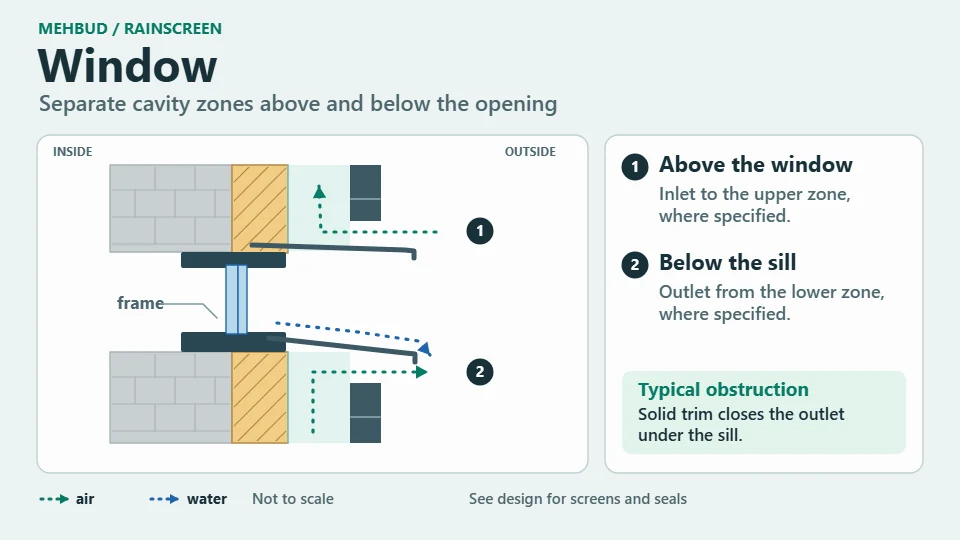
Window junction animation (GIF)

- What blocks the opening. A deep fold in the sill flashing, a solid trim or sealant placed over a specified ventilation opening. Seal the frame joint as designed and check the ventilation opening separately.
- Where the water goes. The top of the sill flashing sheds rain to the exterior. At the head, check the path water takes from the façade junction and how it clears the flashing and drip edge. The water path should account for the reveals and end details.
- What to ask for on the drawing. The locations of local openings, the drainage path, the free dimensions after fitting the trims and perforated profiles, and the positions of the specified protective screens. Agree any screen changes with the project designer.
Manufacturer details can help explain how a system fits together. Dimensions and components from those details apply to the system shown. PREFA window abutment details.
Air intake at the wall base after finishes are installed
In the junction shown, outside air enters through the designed lower opening and the perforated starter profile. A base flashing collects water behind the cladding and directs it to the outer edge. Coordinate the paving and base finish so the finished surfaces clear both paths.
Wall-base air inlet animation (GIF)
- A common obstruction. The base tiles are fitted tight against the starter trim, a solid fold is added or mortar fills the opening. Debris, offcuts or protective film can also remain in the perforations after installation.
- What to check. Measure the remaining clearance, verify the free area of the perforations and compare the finished paving level with the drawing. Where a mesh or other guard is specified, confirm its properties and position.
- What to photograph. Record the starter junction before covering it with cladding and again once the base finish is in place. Show which openings remain clear and where the photograph was taken.
PREFA’s starter detail illustrates how a solid end piece fitted against a perforated starter profile can restrict the designed air inlet. PREFA starter detail.
Air outlet below the parapet coping
In this example, the top of the cavity connects to the outside below the coping. The roof has its own waterproofing junction. The coping sheds rain in the direction of its designed fall, while the cavity discharges air to the exterior at the opening shown.
Parapet air outlet animation (GIF)
- A common obstruction. A deep coping skirt or continuous seal closes the designed outlet by extending down to the cladding.
- What to check. Compare the height of the top cassette, the coping fold, the perforated insert, the membrane termination, roof waterproofing and the water path with the drawing. Pay particular attention to corners, coping joints and changes in parapet height.
- Who should coordinate the detail. The façade and roofing designs meet at this junction. Agree a single section before ordering the trims.
PREFA’s top termination illustrates how the designed outlet remains open once the coping is fitted. Roof construction has its own requirements. PREFA head detail · Ukrainian roof code DBN V.2.6-220:2017.
How to check the ventilation gap before closing the façade
| Junction | Common obstruction | What the section should show |
|---|---|---|
| Window | The sill flashing, head trim or sealant covers a specified local opening. | Each designed opening, the drainage path, the protective screen and the sealed frame joint. |
| Wall base | The cladding, mortar or base trim closes the starter opening. | Air intake, net free area, drainage and finished paving level. |
| Parapet | The coping skirt or a continuous seal closes the air outlet. | Outlet to the exterior, separate roof junction and drainage direction. |
How to calculate the free area of perforations
The outline area of a profile can differ considerably from the area of its holes. Suppose a short section has eight rectangular holes, each 10 × 20 mm. Their total area is 1,600 mm². If a cover plate completely blocks three of them, five remain open, giving 1,000 mm². This example illustrates the geometry. For an actual profile, use the manufacturer’s data, the measured open area and the project requirements. An airflow calculation requires additional inputs.
What to do if an opening is already blocked
Suppose the perforations in the starter trim are visible before the base tiles go on. Once the tiling is finished, the top edge of the tiles covers some holes. Record the location and compare the photographs with the drawing to see what changed. Check whether water can still drain, since the same trim may block both paths. Give the measured clearance and photographs to the person responsible for the detail. They can decide whether to revise the trim, the finish level or another part of the junction.
Site inspection checklist
- On the approved sections, identify each cavity zone, its inlet and outlet, drainage and the fire-protection components.
- Compare the installed components with the drawings before the cladding closes the cavity. Check minimum clearances at constrictions and the position of perforated profiles, membranes and insulation.
- Repeat the check once the sill flashings, base finishes and parapet copings are in place. Record differences in photographs and on a sketch. Obtain approval for any changes before completing the area.
For broader handover checks, use the ventilated façade inspection checklist. If you discover signs of damage during use, record them in the façade defect record (in Ukrainian).
Frequently asked questions
Does the cavity have to run continuously up the building?
The cavity can be divided into zones. The project and the selected system define each zone’s inlets, outlets and air paths. Keep the specified cavity barriers and protective screens in accordance with the approved design.
Is a joint between cladding cassettes enough?
Check what that joint is designed to do. Where the system requires dedicated inlets or outlets, verify their free area and airflow path after all trims are fitted.
Can I add openings after installation?
First establish where the project calls for an opening and what is blocking it. Agree any new opening, cut-out or change to a protective screen with the designer. These changes may affect water drainage, fire protection or cladding performance.
What should I check if moisture appears near the window reveal?
Record when and where the mark appeared. Start by checking the sill flashing, joint seals, membrane termination and drainage. A qualified specialist can assess the concealed assembly and determine the source of moisture through inspection or a technical survey.
Preparing a façade enquiry? Bring elevations, levels and junction sections when discussing Mehbud metal façade cassettes. The overview of ventilated façade requirements (in Ukrainian) gives the wider context.
Related articles
What is glass wool and how to choose it for insulation
How to choose glass wool for a roof, facade, and partition, determine the thickness, and avoid mistakes during installation. Seven answers to frequently asked questions.
Suppliers of thin sheet metal in Ukraine
Where to look for galvanized sheet, coil, and strip. Overview of suppliers and a list of parameters for requesting a price and checking a batch.
Architectural trends in medical facility facade design
Modern medical facility facade trends: ventilated metal systems, infection control, fire safety, and patient psychological comfort.