
Sliding gates open along the fence. Installation requires a clear opening, a free side zone for the full travel distance of the leaf, and a foundation engineered for its mass and wind load. Prior to ordering, measure the site, select the direction of travel, and request an installation drawing with complete dimensions. This is particularly critical for cantilever gates, which feature a tail extension behind the visible leaf.
Automation can be incorporated immediately or added later, provided the drive location and cable runs are agreed upon in advance. The guide below will help you prepare measurements, compare designs, and accept the finished driveway installation.
Which Sliding Gates Suit Your Property
| Gate Type | What to Check |
|---|---|
| Cantilever | The leaf beam runs on roller carriages located to the side of the driveway. Verify space for the tail extension, the foundation for the carriages, and ground clearance along the entire travel path. |
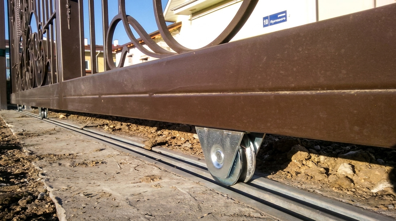
| Tracked (Track-guided) | Wheels travel along a track set into the driveway. Check foundation levelness, water drainage, and clear access for cleaning sand, leaves, and snow. |
| Overhead (Suspended) | The leaf moves along an overhead beam. Check maximum vehicle height clearance and structural feasibility for support posts. |
If space along the fence line is limited, evaluate a swing gate configuration separately. Swing gates require a clear sweep area, and on sloped driveways, bottom clearance must be checked throughout their arc. In the “Mehbud” gate catalog, you can compare infill options for both configurations.

What to Measure Before Ordering Gates
- Clear opening width and height. Measure the distance between finished posts. Note any potential projections. For narrow streets, check the turning radius of the largest vehicle that will use the driveway.
- Clear length to the left and right. Mark the edge of the opening and any nearby obstructions along the line of movement. Show on your plan fence corners, pedestrian gates, downspouts, protruding posts, trees, and utility boxes. Request gate dimensions in both open and closed positions, including tail extension, stops, and service clearances.
- Finished ground levels. Provide the surveyor with the finished height of future paving or asphalt, elevation changes along the gate travel, and cross slopes across the driveway. This allows verification of clearance under the leaf after landscaping and helps plan drainage.
- Pedestrian routes. Where possible, position the pedestrian gate outside the gate travel zone and motor access area. Indicate on the plan which way it opens and how it is approached from the yard.
- Foundation and utilities. Detail the structural material of existing posts, the routing of pipes and cables, and the power supply point. Specify space requirements for motor servicing and manual override access.
How to Check the Driveway and Opening Direction on a Sketch
Draw a top-view diagram showing two key paths: the vehicle trajectory and the gate leaf travel to its fully open position. If entering at an angle from the street, note the road width and the distance to the opposite curb or wall. For properties where snow is piled in winter, mark that zone on the plan. For cantilever gates, the footing is placed to the side, so its footprint must be verified separately from the travel space of the moving leaf.
Measurement Example. Suppose the clear opening width is 3.8 m, and there is 5.4 m of free space along the opening side up to the fence corner. If the technical drawing for a specific model requires 5.7 m for the open leaf, you are short by 30 cm. At this stage, you can check opening in the opposite direction or consider a different gate type. Dimensions in this example are illustrative and should be confirmed against the drawing of your selected kit.


What Should Be Included in the Design and Package
Gate Leaf, Supports, and Hardware
Confirm height, leaf infill, and color before structural frame calculations. Solid panels increase privacy, but their area must be factored into wind load calculations. For cantilever systems, verify that the package includes the bottom track, roller carriages, top guide rollers, end catchers, and travel stops. The system designer or supplier is responsible for foundation, support post, and fixing engineering under the contract. Hardware is selected to match the geometry, weight, and operating conditions of the leaf.
Cost Estimate and Work Stages
Request pricing based on a single unified scope of work. Itemize frame and infill, hardware, posts and foundation, operator, safety devices, delivery, installation, and commissioning in the estimate. Clarify who restores ground surfaces after conduit trenching and what maintenance covers.
Installation is planned around finished driveway level marks. First, agree on footing locations and conduit runs, then verify footing load readiness, install the leaf, and adjust hardware. The operator is installed only after verifying smooth manual travel. Cable cross-section, circuit protection, and laying methods are determined by electrical engineering drawings and operator manual specifications.
What to Agree On if the Fence Is Already Installed
Provide the surveyor with photos of existing posts from both sides along with foundation details. Request that drawings indicate which existing supports can be reused and where new ones are required. If yard paving levels will be raised later, lock that future elevation mark into the project spec. For single orders, it is convenient to coordinate the wicket door, sliding gate, and adjacent fence panels simultaneously to ensure matching louver lines, joint alignments, and sample-verified coating colors.
Selecting Automation and Safety Features
Before selecting a drive operator, inform the supplier of the leaf length and weight, expected duty cycle/frequency of operation, operating temperature range, and site entry conditions. The Nice manual for the ROBO600 operator details specific limits on dimensions, weight, and duty rating. Always cross-check project data against the operator manual for the exact model proposed.
Sliding gates present entrapment hazards at the receiving post, along the back fence, and near the moving gear rack. The HSE guidelines on powered gate safety address hazardous zone guarding, force limitation, safety edges, and presence sensors. Safety equipment specification and tuning must be performed by a qualified site risk technician. Photoelectric cells should be evaluated alongside zone protection along the entire travel path.
Clarify how to operate manual release during power outages, where it can be accessed, and how to re-engage automatic mode. If the driveway is the sole entry to the property, establish access procedures for power loss prior to installation.
If automatic closing mode is required, explicitly request documentation on how the system responds to obstacles during opening versus closing. Confirm whether selected modes persist after power restoration and who holds operational settings responsibility. For shared driveways serving multiple properties, inform the installer of peak traffic times to size equipment for maximum load cycles.
Sliding Gate Acceptance Checklist
- Cross-check model, infill, dimensions, and hardware against the approved specification.
- Have the installer demonstrate full leaf travel. Verify clearance over finished paving, operation of stops and catchers, and unobstructed pedestrian door access.
- Request a demonstration of safety stop or reverse functions upon activation of protection devices. Operating force testing and safety device certification must be performed by a technician using appropriate test gear.
- Test manual opening with main power disconnected alongside the installer, then confirm proper re-engagement to automatic operation.
- Obtain user manuals, wiring diagrams or equipment lists, warranty terms, and maintenance schedules. Confirm point of contact for tracking issues, misalignment, or sensor faults.
During operation, keep the gate travel area clear, remove snow and debris promptly, and inspect limiters and sensors according to manual instructions. If binding occurs, suspend use until inspected. When replacing infill materials, approve updated mass, wind load, and operator recalibration in advance.
I am text block. Click edit button to change this text. Lorem ipsum dolor sit amet, consectetur adipiscing elit. Ut elit tellus, luctus nec ullamcorper mattis, pulvinar dapibus leo.
Related articles
When you don’t need to put up a fence and what restrictions to check
When you can do without a solid fence, how to check boundaries and restrictions, and when to postpone installation. Checklist and answers to frequently asked questions.
Neuroarchitecture of Fences: How the Height and Pitch of Fence Lamellas Affect the Anxiety Level of Cottage Town Residents
How fence height and slat pitch affect anxiety in cottage towns. Discover neuroarchitecture, louver fences, and how they balance privacy and safety.
TOP Medical Laboratory Networks in Ukraine: Architecture, Infrastructural Innovations, and Market Leaders Rating
Overview of top medical lab networks in Ukraine 2026: Synevo, Dila, CSD LAB. Architecture, ISO 14644 cleanrooms, accessibility, and energy independence.