Laser metal cutting is a non-contact thermal cutting process using a focused beam along a given trajectory. It is suitable for external contours, holes, and complex parts, but it does not guarantee the absence of burrs, deformations, or the need for subsequent processing. The result is determined by the material, thickness, equipment, process gas, and drawing requirements.
For the customer, it is important to agree not only on “laser cutting” but also on tolerances, edge condition, surface protection, and subsequent operations. Below, we explain the operating principle, capabilities, and limitations of the technology, as well as the data that should be provided to the manufacturer.
How Laser Metal Cutting Works
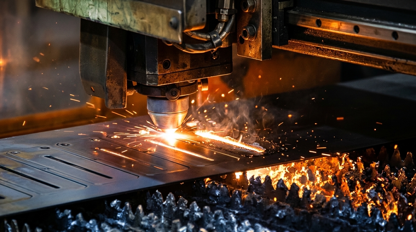
Optics focus the radiation onto the workpiece. In the cutting zone, the metal is heated, and during the common fusion cutting process, the molten material is removed by a gas jet. A CNC (Computer Numerical Control) system moves the cutting head and/or the workpiece according to the program. The principle and components of the process are described by TRUMPF in their laser cutting guide.
Gas helps remove the melt and affects the edge condition. It is chosen based on the material, mode, and requirements for subsequent processing, rather than by a universal recipe.
| Process | What is important for the result |
|---|---|
| Fusion cutting with nitrogen or argon | The gas removes the melt without supporting an oxidation reaction. This mode is used when an oxide-free edge condition is important. |
| Oxygen laser cutting | The oxidation reaction adds energy to the process. The state of the oxide layer must be considered before painting, welding, or other operations. |
Differences between gas modes are given in TRUMPF’s fusion cutting explanation. This is an overview of principles, not a table of pressure, speed, or specific machine settings.
Non-contact means the absence of a mechanical cutting tool in the cut zone, but not the absence of heating. Fraunhofer IWS describes a small heat-affected zone, as well as the process’s dependence on radiation absorption and the thermal properties of the material. Thermal deformation must still be evaluated for thin or narrow parts.

What Equipment Is Used
Sheet cutting uses systems with various sources, including CO₂ and fiber lasers. A fiber laser is a type of solid-state source; it should not be opposed to all solid-state lasers as a separate incompatible category. The structure of such sources is explained by IPG Photonics.
When choosing, evaluate the working format, list of materials and thicknesses, quality on the required geometry, gas supply, cooling, smoke extraction, loading, and unloading. Source power alone does not determine accuracy, economy, or full productivity. Optics, cutting head, control, and technological preparation are also important.
What Metals and Thicknesses Can Be Cut
Typical tasks include cutting carbon and stainless steel, aluminum, and its alloys. Copper and brass can also be processed on equipment designed for the respective materials. High reflectivity and thermal conductivity complicate mode selection, but do not mean a general prohibition: IPG Photonics describes cutting reflective metals with application-specific parameter tuning.
There is no single “20 mm for any setup” limit. The permissible thickness is checked for a specific material grade, source, gas, and configuration. For example, in the technical data of TRUMPF TruLaser Series 5000 for the TruFiber 6001 configuration, the maximum carbon steel thickness is stated as 25 mm. This is a characteristic of the specified configuration, not a recommendation for another machine or a guarantee of the required quality for any contour.
The maximum thickness table does not replace the agreement of tolerances, small holes, narrow bridges, and edge conditions. For a critical or new part, it is advisable to agree on a test sample.
Thin, Galvanized, and Painted Sheet
On thin sheets, the sequence of cuts, heat input, workpiece support, and preservation of small elements are important. Lesser thickness does not eliminate the risk of warping or surface damage.
For galvanized sheet, polymer coating, or protective film, provide exact data to the manufacturer. It is necessary to confirm the material’s suitability for laser processing, the permissibility of the film, and edge requirements after cutting. Do not use unknown coatings as regular “clean metal.” For parts to be painted, pre-agree on edge preparation and bare substrate protection.
Advantages and Limitations of the Technology
- Contour flexibility. Numerical control allows changing part geometry without making a separate die for each contour. At the same time, a verified control program is required.
- Repeatability. It is useful for series if the material, equipment condition, and mode are stable. The numerical tolerance is specified in the drawing and agreed upon with the manufacturer.
- Rational nesting. Part layout on the sheet can reduce waste. Real yield depends on shape, gaps, technological bridges, and scrap suitability.
- Opportunity to reduce post-processing. A quality mode can yield an edge suitable for the next operation. This must be verified against product requirements.
Possible limitations include thermal effects, dross and burrs, roughness, beam entry traces, dimensional deviations, traces of technological bridges, or coating damage. Even the special Quality Cut Package from Bystronic is described by the manufacturer as a solution for virtually burr-free cutting, rather than as an unconditional absence of defects on any material.
Do not evaluate delivery time and price solely by linear cutting speed. Preparation, piercing, number of contours, gas, nesting, part removal, and cleaning also affect the order. A single efficiency figure without specifying the source and measurement limits does not describe the economics of the entire installation.
What to Check After Cutting
- Dimensions, holes, and element locations according to the drawing.
- Edges: burrs, dross, roughness, oxide layer, and bridge locations.
- Flatness, undesirable twisting, and coating condition.
- Readiness for bending, welding, painting, or assembly.
If necessary, provide for deburring, cleaning, or other processing. Common problems are discussed in an article about sheet metal product defects. Subsequent bending must be accounted for already at the unfolding stage: see also the material on sheet metal bending.
What to Prepare for a Laser Cutting Order
- Material: grade, thickness, coating, and sheet supply source.
- Geometry: an approved vector file, such as DXF/DWG, if the manufacturer accepts this format, and a drawing with control dimensions and units. For bent parts, clarify who prepares and checks the flat pattern.
- Quantity: number of parts, batch size, and requirements for marking or packaging.
- Quality: required tolerances, visible surface requirements, edge requirements, and permissible technological traces.
- Subsequent operations: bending, welding, painting, fastening. Agree on necessary cleaning and protection after cutting.
- Acceptance: control sample, verification method, and agreed composition of the finished order.
Laser Processing Safety
Laser cutting is performed on designated equipment by trained operators. Functional safety systems, smoke extraction, and fire risk control are required. Do not bypass interlocks and do not conclude that observing the beam is safe based solely on videos or photographs.
HSE classifies laser cutting as a process that generates harmful aerosols; UCL highlights radiation, fire, and smoke risks, especially during maintenance. These are general guidelines, not a replacement for machine instructions and workplace assessment.
Frequently Asked Questions
Can aluminum, copper, and brass be cut with a laser?
Yes, using equipment and modes suitable for the specific alloy and thickness. Reflectivity must be considered when selecting the source and optics.
Does the part require processing after laser cutting?
This depends on the resulting edge and the subsequent operation. Oxide cleaning, deburring, or removal of bridge traces should be agreed upon in advance.
What is the maximum metal thickness?
It is determined by the technological table of the specific equipment configuration for the required material and gas. There is no universal limit for all lasers.
Is an image or sketch sufficient for accurate manufacturing?
An image helps discuss the concept, but production requires approved geometry, dimensions, units, and quality requirements. File preparation and unfolding are coordinated with the manufacturer.
Related articles
How to Fix Dents in Metal: Repair or Replacement
Dents on metal not only degrade its aesthetic appearance but also trigger the gradual peeling of the protective coating from the steel base — which is…
Top Façade Insulation Companies in Kyiv (2026): Expert Ranking and Review
Detailed overview of the best façade insulation companies in Kyiv. Comparison of prices, reviews, services, and materials. How to choose a reliable contractor without overpaying.
Where to buy a plot of land?
Buying a land plot is a significant decision that requires a thoughtful approach. You should not rush either at the stage of choosing the land or…