
Modern landscape design and engineering preparation of territories require an exceptionally comprehensive approach to space arrangement, where engineering networks harmoniously combine with architectural elements. The fencing of the site and pedestrian zones are no longer considered separate, isolated components of landscaping. They act as a single ecosystem that functions under the constant influence of aggressive environmental factors. The greatest threat to the structural integrity and durability of infrastructure objects is water. Regular atmospheric precipitation, intensive snow melting, and surface runoff can critically destroy the concrete foundation of the fence in just a few seasons, cause irreversible subsidence of the paving of paths, and disrupt the aesthetics of the entire site. That is why the integration of an effective surface drainage system is not just a desirable option or decorative element, but a strict engineering necessity regulated by building codes. This report offers a comprehensive analysis of the principles of organizing linear drainage, the specifics of the interaction of hydraulic structures with modern metal fences, the choice of materials, as well as a detailed review of installation technologies and common mistakes during the operation of such systems.
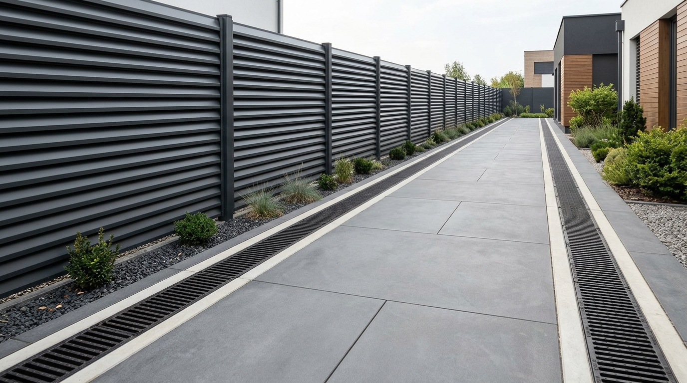
Specifics of modern metal fences and their vulnerability to moisture
Modern premium-segment enclosing structures differ radically from traditional blind walls, concrete slabs, or simple meshes used in the last century. Market analysis demonstrates that leading manufacturers offer high-tech solutions that combine exceptional mechanical strength, durability, and thoughtful aerodynamics. To understand the importance of effective drainage, it is first necessary to analyze the structures themselves in detail, as their architecture and material science features directly affect the distribution of water flows on the site and the level of load on the foundation.
The main types of modern metal fences are ventilated systems assembled from individual profiled elements called lamellas. Several basic modifications have gained the greatest popularity. The “Rancho” model range imitates a classic wooden fence made of horizontal poles, but is manufactured from durable galvanized steel with a protective polymer coating. Lamellas can be installed in one or two rows, forming different levels of transparency and ventilation. There are also wide modifications where the lamella width reaches one hundred and eighty millimeters, creating a more massive and solid appearance. Thanks to the presence of gaps, such a fence does not create the effect of a solid sail wall, allowing air masses to circulate freely, which significantly reduces the wind load on the load-bearing pillars.
The “Blinds” model range is distinguished by a unique diagonal placement of lamellas. They are installed at a precisely calculated angle, which guarantees absolute privacy of the territory, as the site cannot be viewed from the outside, but at the same time, excellent cross-ventilation and sufficient illumination for plants are maintained. These series include various options, such as Premium, Classic, Standard, Exclusive Lego, and modifications with an increased lamella width Exclusive XL, which allows you to choose the optimal solution for any architectural style.
The innovative “Rombo” series uses lamellas with a unique geometric profile. Wide vertical edges form the main plane of the structure, and specially beveled top and bottom edges maximally reduce the width of the gaps. Visually, such a fence looks like an absolutely solid, monolithic wall, but it remains fully ventilated and permeable to sunlight. The Light modification features even more refined lines and reduced weight while maintaining all protective functions.
All these products are made of high-quality galvanized steel, the thickness of which strictly varies from forty-five hundredths to seven tenths of a millimeter. A mandatory stage of production is the application of a protective and decorative polymer coating, which can be glossy, matte, or made using the high-precision Printech offset printing technology to perfectly imitate the texture of wood or stone. This coating reliably protects the metal from aggressive corrosion, the destructive effect of ultraviolet radiation, and extreme temperature drops, guaranteeing a service life of over thirty years.
However, despite the exceptional climatic resistance of the above-ground metal part of the fence itself, its Achilles’ heel remains the concrete base. Heavy steel sections require the arrangement of a reliable strip foundation or powerful point supports for metal pillars. During rain, water draining from the wide planes of metal lamellas, as well as surface runoff from adjacent paths, concentrates at the base of the fence. If this water constantly flows under the foundation, a critical saturation of the soil with moisture occurs. In winter, when the temperature drops below zero, the water in the soil pores freezes and expands, leading to the phenomenon of frost heaving of the soil. The heaving forces generate such powerful pressure that they are capable of pushing out, bending, and breaking the concrete strip. This inevitably leads to the skewing of metal pillars, deformation of expensive fence sections, and a complete loss of the geometry of the fencing, which will require major repairs. That is why the absolute protection of the foundation begins with the creation of a reliable hydraulic barrier right on the ground surface.

Principles of designing a surface drainage system
Surface drainage is a complex engineering network conceptually designed for the fast, controlled collection and removal of atmospheric precipitation from hard artificial surfaces. The main goal of this system is to prevent the flooding of capital structures, preserve the integrity of foundations, and avoid the degradation of landscape forms. In the context of the professional arrangement of the perimeter of a private or commercial site, especially along massive metal fences and adjacent pedestrian paths, the most appropriate and effective engineering solution is the implementation of a linear drainage system.
The linear drainage architecture consists of a continuous network of recessed channels (trays or gutters), which are reliably covered on top with strong protective grates. These channels stretch along the entire calculated path of water collection, forming a kind of artery for transporting moisture. Unlike point drainage, which is able to collect water only in localized, specific places (for example, directly under vertical downspouts descending from building roofs), linear drainage has the ability to intercept a continuous, wide flow of water formed on the entire plane of a paved path or asphalt area. This approach has a colossal technological advantage: it significantly minimizes the volume of complex earthworks, since there is no need to create multi-level envelope slopes of the coating converging to one central receiving point. Instead, for the correct operation of a linear system, it is enough to provide a simple, one-sided or two-sided flat slope of the path surface, directed directly towards the line of receiving trays.
The spatial placement of the drainage main is most often designed on the strategic boundary between the hard paved surface of the path and the concrete foundation of the fence, or as a separator between the path and the soft lawn. Such a thoughtful arrangement creates an insurmountable hydraulic barrier for surface water. Atmospheric water falling on a hard surface rolls down the given slope under gravity, freely penetrates through the holes of the protective grates into the recessed gutters, and is quickly transported outside the site. The end point of this route can be an accumulating collector well, a main city storm sewer, or a specially equipped discharge zone into a natural body of water. The main result is that the water is physically diverted from the territory, never reaching the hydrologically vulnerable concrete plinth of the fencing.
The hydraulic efficiency of a linear system is in a direct mathematical dependence on two key factors: the throughput capacity of the selected trays, which is determined by their internal hydraulic cross-section, and a correctly formed longitudinal slope of the entire route. The laws of classical hydrodynamics dictate that the water inside the channel must move by gravity at a strictly defined speed. This speed must be high enough to provide a self-cleaning effect for the system, preventing the settling of heavy particles of silt, dirt, and fine sand on the bottom of the channel. At the same time, the flow rate should not be excessive so as not to cause hydraulic overflows at turns or at connections to sand traps. Engineers achieve a perfect balance by creating a natural stepped slope of the bottom of the excavated trench, or, in cases of working on perfectly flat areas, use specialized trays with an internal cascading height difference, which independently form the necessary angle of inclination of the water mirror.
Classification of mechanical loads of drainage systems
One of the most critical and responsible stages of the engineering design of surface drainage is a correct, scientifically sound calculation of the mechanical loads that the system is capable of withstanding without the risk of structural failure. The choice of specific elements of the drainage network is based on a strict standardization system that divides products into six main classes depending on their ability to withstand the maximum permissible weight pressure and dynamic impacts. Statistics show that neglecting this basic parameter or attempting unjustified savings is the most common cause of catastrophic and premature failure of the system, which entails the need for a complete reconstruction of the object.
Table of operational load classes for surface drainage systems
| Load classifier | Maximum weight | Typical infrastructure areas of application |
| Class A-15 | Up to 1.5 tons | Exclusively pedestrian zones, bicycle paths, park alleys, private yards without the slightest risk of vehicle entry, green zones, and lawns. |
| Class B-125 | Up to 12.5 tons | Entrances to private garages, city sidewalks, parking areas for passenger cars, adjoining territories of apartment buildings. |
| Class C-250 | Up to 25 tons | Fortified roadsides, parking lots of large shopping centers, territories of car services, areas with periodic and non-intensive traffic of commercial vehicles. |
| Class D-400 | Up to 40 tons | Public city roads, gas stations, logistics infrastructure hubs with regular traffic of heavy trucks. |
| Class E-600 | Up to 60 tons | Large industrial facilities, factory territories, closed-type logistics and warehouse terminals, transport hubs with ultra-high loads. |
| Class F-900 | Up to 90 tons | Airport territories, runways, seaport cargo terminals, military bases, areas of continuous operation of ultra-heavy tracked and wheeled special equipment. |
For arranging effective drainage directly along fences around private households, engineers most often consider the first three classes of strength. Class A-15 is basic and certainly the most economically attractive solution on the market. However, it has extremely strict limitations regarding use. If the drainage system is designed and installed exclusively along a closed pedestrian path or terrace, where physical entry of any vehicle is impossible under any circumstances, trays of this light class will be quite enough to perform the tasks assigned to them for collecting rainwater.
However, the engineering paradigm radically changes if the projected path borders the entrance gate zone to the territory or adjoins a parking lot. Even a one-time, accidental run-over by a wheel of an ordinary passenger car on a grate belonging to Class A-15 will highly likely lead to its irreversible plastic deformation, destruction of fragile locking fasteners, and splitting of the walls of the tray itself. In such transitional, potentially dangerous zones, building codes categorically require the use of products that meet the B-125 standard. This class provides a significant technological safety margin and is guaranteed to withstand not only the constant static weight of a parked passenger car but also, more importantly, sharp dynamic loads. Such loads include colossal shear forces arising during emergency braking, rapid acceleration, or maneuvering with turned wheels directly on the surface of the drainage grate.
In more complex cases, when the metal fence directly borders an active carriageway of a municipal street, or if heavy equipment (e.g., multi-ton sewage trucks, garbage trucks, or trucks with building materials) is regularly planned to enter through the gates, experts strongly recommend raising the level of structural reliability of the system to Class C-250 or even D-400. Using stronger reinforced trays combined with massive cast-iron grates will allow the owner to avoid catastrophic failures of the road surface and costly major repairs of the entire drainage line just a year after commissioning the facility.
Material science: selecting drainage trays
The global market of building materials offers three fundamentally different groups of raw materials for the manufacture of drainage channels: specialized engineering plastics, classic vibro-pressed concrete, and high-tech composite — polymer concrete. Each of these materials has a unique set of physicochemical properties that strictly determine its behavior during years of operation, chemical resistance, and the specifics of performing installation work on the site.
Plastic drainage systems are made of adapted high-pressure polymers with the addition of special stabilizers. Their indisputable and most important advantage is the extremely low weight of the finished product. The weight of one linear meter of a plastic gutter usually ranges from three to fifteen kilograms, which allows one person to effortlessly transport, unload, and lay the elements without involving expensive specialized lifting equipment. On a microscopic level, the plastic structure provides a perfectly smooth, mirror-like inner surface of the tray. From the point of view of hydrodynamic laws, this means the presence of a minimum coefficient of hydraulic roughness. Due to this property, atmospheric water flows through the channel much faster, washing away fine organic debris, dust, and sand, which virtually eliminates the silting of the system even at minimal slopes. Engineering plastic is an absolutely inert material: it is not susceptible to any forms of corrosion and does not react in any way to prolonged contact with chemically aggressive substances, such as anti-icing salt reagents, acid rain, or spilled fuels and lubricants. In addition, such lightweight channels are very convenient to adapt to non-standard site sizes — they can be quickly cut with a regular fine-toothed hand hacksaw right on the construction site. However, the main and insurmountable drawback of plastic remains its significantly limited load-bearing capacity. This material is prone to significant linear thermal expansion in the heat and becomes somewhat brittle in severe frosts. It can instantly crack under significant, uncalculated mechanical pressure, so its application is mainly and strictly limited to pedestrian zones.
Concrete products are massive, monolithic structures manufactured by intensive vibro-pressing of a concrete mixture reinforced with steel rods. These are real heavyweights in the world of drainage systems. Their mass can exceed a hundred kilograms per linear meter, making manual installation physically impossible and without alternative requiring the use of cranes or excavators. Traditional concrete perfectly withstands colossal static and dynamic loads without any deformations, thanks to which its service life at industrial facilities can reach fifty years. However, the inner surface of the concrete channel has a pronounced porous and microscopically rough structure. Over time, organic dirt accumulates in these microscopic craters, which gradually reduces the calculated flow rate and creates an ideal environment for the growth of moss and algae. Classic concrete also has a certain, inherent ability to absorb moisture. If the drainage system does not have time to dry completely before the onset of severe, sharp frosts, the water remaining in the surface pores crystallizes. Ice crystals tear the upper layers of the material, leading to gradual flaking, crumbling of the surface, and exposure of the internal steel reinforcement.
Polymer concrete systems are objectively the pinnacle of the technological evolution of drainage materials. They represent an ideal engineering compromise that completely eliminates the critical flaws of both light plastic and massive concrete. For their production, instead of traditional Portland cement as a binding element, extremely strong synthetic resins (polyester or epoxy) are used. These resins are mixed in a vacuum environment with fractionated quartz sand, granite chips, and other mineral fillers. As a result of a complex polymerization reaction, an extremely dense monolith devoid of air pockets is formed. The water absorption level of polymer concrete practically approaches zero, making it absolutely immune to destructive freeze-thaw cycles. Thanks to the mineral framework, it has mechanical strength that is comparable to or even significantly exceeds the strength of traditional heavy concrete, but at the same time, its geometric weight is half as much. The inner walls of polymer concrete trays are as perfectly glossy and smooth as their plastic counterparts, guaranteeing consistently high hydraulic efficiency throughout their entire service life. Although the initial purchase cost of polymer concrete systems is noticeably higher, their phenomenal durability, absolute resistance to aggressive chemicals, and operational versatility make them the most optimal and economically justified choice for equipping premium territories around expensive metal fences.
Table of comparative analysis of drainage material characteristics
| Physical and operational parameter | Polymer plastics | Vibro-pressed concrete | High-tech polymer concrete |
| Resistance to mechanical loads | Low to medium | Ultra-high | Consistently high |
| Total weight of structural elements | Ultra-light structure | Ultra-heavy, massive | Moderate, balanced |
| Hydraulic smoothness of the inner surface | Perfect, mirror-like | Pronounced rough, porous | Perfect, mirror-like |
| Chemical resistance to aggressive environments | High protection level | Medium, vulnerable to acids | Ultra-high protection level |
| Level of complexity of installation work | Minimum (performed manually) | Maximum (requires cranes) | Moderate (allows manual installation) |
| Capillary water absorption rate | Absolutely zero | Always present | Practically zero, minimal |
Synergy of drainage and waterproofing of the fence foundation
Installing surface drainage trays radically and effectively solves the problem of rapidly removing the bulk of rainwater. However, not a single, even the most perfect open system is capable of guaranteeing one hundred percent collection of every drop falling from the sky. A certain amount of moisture inevitably seeps through the technological gaps of the paving, joints between paving slabs, or simply falls directly onto the ground near the base during powerful slanting downpours. In order to provide a full-fledged, multi-level protection for the concrete foundation of a metal fence, surface drainage must function in a strict, inextricable conjunction with the complex waterproofing of the concrete base.
From an engineering point of view, concrete has a spongy, branched capillary structure consisting of millions of microscopic channels. When an unprotected fence foundation comes into contact with moist soil, the physical effect of capillary suction is instantly triggered: water molecules begin to slowly but steadily rise upward through the thickness of the concrete, easily overcoming gravity. If this migrating moisture reaches the steel reinforcement, which is the load-bearing frame of the structure hidden deep inside, a process of active and irreversible corrosion will begin. During rusting, metal chemically expands, significantly increasing in volume. This creates colossal internal pressure that literally tears the concrete monolith from the inside, forming deep structural cracks and chips. In addition, moisture that has risen by capillary action to the very top of the plinth begins to directly contact the lower steel fasteners of the metal fence lamellas, provoking oxidation and rusting even on galvanized surfaces provided there is micro-damage to the polymer coating.
To reliably prevent these destructive hydrophysical phenomena in construction, two independent protection contours are used: horizontal and vertical waterproofing. Horizontal waterproofing is methodically laid as an interlayer between the upper plane of the concrete foundation and the above-ground brick or metal part of the fence itself. Its only, but critically important goal is to rigidly cut off the capillary rise of moisture up to the metal elements. Vertical waterproofing, in turn, covers all the walls of the foundation located underground with a continuous carpet, reliably blocking the penetration of aggressive groundwater from the side.
Modern chemical and building technologies offer specialists a wide arsenal of insulating materials, each of which has its own mechanism of action. Coating waterproofing creates an elastic, absolutely seamless, and waterproof film directly on the concrete surface. It is realized by manual or machine application of modified bitumen, polymer, or complex rubber-bitumen mastics in several consecutive layers using rollers, brushes, or broad brushes. The total thickness of the protective layer after complete drying should be from two to four millimeters. This method is relatively affordable financially and easily adapts to the most complex geometric forms of the foundation, although its overall service life is usually up to ten years, after which the initial elasticity is gradually lost due to polymer aging processes.
Roll-fed or pasting waterproofing involves the use of strong materials based on fiberglass fabric, fiberglass, or polyester, which are deeply and evenly impregnated with polymer-bitumen binders. These materials are fused to the surface using an open flame of a gas burner or glued onto special cold primers. It is extremely important from a technological point of view to strictly observe the installation rule with a mandatory overlap of adjacent sheets on each other by at least ten centimeters. Such a multi-layer, reinforced protection is characterized by extremely high reliability and durability, which makes it the gold standard for equipping the foundations of heavy metal fences.
Penetrating waterproofing functions at the microscopic level and radically, permanently changes the crystalline structure of the concrete itself. Special chemically active mixtures containing high-grade Portland cement, finely dispersed quartz sand, and patented active additives are applied to the previously abundantly moistened foundation surface. Thanks to osmotic pressure, the active substances penetrate deep into the pores and enter into a complex chemical reaction with the free calcium salts inside the concrete. As a result, strong, insoluble needle-like crystals are formed, which tightly plug the capillaries to an incredible depth of up to fifteen centimeters. This integrated barrier does not allow drop moisture to pass even under colossal hydrostatic pressure, but leaves the concrete with a unique ability to pass vapor molecules, that is, to “breathe”.
Injection technologies are the most high-tech and are mainly used for the emergency repair of existing cracks and defective seams of an old foundation. With the help of special powerful pumps, polyurethane, epoxy, or acrylate resins are pumped deep into the body of the concrete structure under ultra-high pressure, which instantly harden upon contact with moisture, completely and reliably blocking any potential pathways for the migration of destructive moisture.
To achieve maximum, uncompromising reliability, leading engineers always recommend using a combined approach: the surface of the underground part of the strip fence foundation is first carefully treated with penetrating compounds for internal protection, after which a layer of coating mastic is applied, and this sandwich is additionally protected with a roll membrane. This saves the waterproofing layer from accidental mechanical damage by sharp stones contained in the soil during the backfilling of the trench.
Deep drainage as a hydrological safety net for difficult soils
In hydrogeological situations where the construction site is geographically located in a natural lowland, is characterized by a consistently high level of groundwater, or is based on heavy clay or loamy soils with extremely low capacity for natural water filtration, exclusively surface drainage using trays may objectively not be enough for complete safety. Atmospheric water that has fallen on the lawn and failed to be intercepted by surface trays inevitably stagnates in the soil directly around the fence foundation, turning the load-bearing layer into unstable, plastic mud unable to withstand the weight of the structures. In such complex cases, the linear surface collection system must be supplemented by an underground trench drainage system.
The fundamental principle of operation of a wall or trench drainage system is the artificial creation deep underground of an extensive network of channels with extremely low hydraulic resistance. Water, in accordance with the laws of physics, always looks for the path of least resistance and gravitationally rushes precisely into this zone, leaving the surrounding soil relatively dry. The arrangement technology involves digging a deep trench parallel to the entire mass of the fence foundation. The depth of this trench is calculated in such a way that its bottom is necessarily below the level of the sole of the foundation itself, which allows effectively intercepting the water before it rises to the base of the fence.
Critically important for durability is the complex multilayer structure of filling this trench, which acts as a powerful two-layer filter. First, on the carefully leveled bottom of the trench with a pre-compacted sand cushion, a special synthetic canvas — geotextile — is laid. Its density should usually be from two hundred to two hundred and fifty grams per square meter. The main engineering function of the geotextile is to seamlessly pass water molecules inside the system while simultaneously acting as a microscopic sieve that traps the finest particles of soil, clay, and silt. If it weren’t for this barrier, the dirt would very quickly clog the system and put it out of action forever. Next, over the spread geotextile, a volumetric layer of carefully washed granite crushed stone of a large fraction (usually from twenty to forty millimeters) is poured. Deep into this crushed stone, a special corrugated drainage pipe made of strong polymers is neatly laid, having a multitude of small holes — perforation — on its surface. The pipe must be laid with a uniform slope verified by a level (not less than half a percent) toward the final point of water discharge.
After laying, the pipe is covered on top with another solid layer of crushed stone (about twenty-thirty centimeters high), after which the free edges of the geotextile canvas are carefully wrapped overlapping (with an overlap of at least fifteen-twenty centimeters), similar to a postal envelope. This completely and hermetically isolates the crushed stone and pipe from direct contact with the surrounding earth. On top, this entire engineering system is covered with a protective, leveling layer of sand (five-ten centimeters thick) and fertile soil. The water located in the waterlogged soil encounters this highly permeable barrier on its way, seeps through the pores of the geotextile, passes through the voids between the stones of crushed stone, enters through the perforation directly inside the corrugated pipe, and is quickly and by gravity drained into an accumulation or inspection well for further pumping out by pumps.
The synchronous, coordinated operation of the surface linear and deep trench drainage creates an absolutely dry, stable zone around the entire perimeter of the fence foundation, completely neutralizing any risks of frost heaving and guaranteeing perfect, unchangeable geometry of the lines of an expensive metal fence for many decades of continuous operation.
Technology and stages of precision installation of surface drainage systems
Even the most expensive drainage systems, made of innovative polymer concrete and equipped with massive cast-iron grates, instantly lose their effectiveness and quickly deteriorate with the slightest violation of their installation technology. The process of proper installation requires jewel-like precision from contractors, strict, uncompromising adherence to geodetic levels, and the use of exclusively correct fixing and sealing mixtures.
The process of professional installation of linear drainage invariably begins with detailed marking of the future route using metal pegs and tightly stretched cords. It is extremely important in advance, even before starting earthworks, to plan an unobstructed path for the water from the highest topographical point of the site to the final connection point to the central city storm sewer or a local sand trap.
The next technological step is accurate excavation of soil or cutting the existing pavement. The overall dimensions of the excavated trench must significantly, with a strictly defined margin, exceed the external dimensions of the trays themselves. The depth of the trench is mathematically calculated as the full height of the selected tray plus an additional ten to fifteen centimeters of space, allocated exclusively for the arrangement of a reliable base. The width of the earth channel must provide an additional ten-fifteen centimeters of free space on each side from the outer vertical edges of the gutter. This excess space is not a mistake; it is critically and vitally necessary to create a powerful concrete “clip” (the so-called jacket), which in the future must rigidly and monolithically fix the product in space, making its movement under the influence of loads impossible.
After carefully compacting the earth bottom with a vibrating plate, a shock-absorbing cushion of dry sand-cement mixture or fine crushed stone is formed on it. On top of this prepared cushion, experienced professionals always strongly recommend laying a continuous layer of vapor barrier film (most often dense polyethylene or two layers of building parchment are used). This inexpensive film performs a crucial function of a hydraulic barrier that completely prevents the rapid leakage of cement milk from the concrete mixture into the dry soil during pouring. Retaining moisture in the mortar allows the concrete to systematically, without drying out, gain its maximum brand strength.
Next, a solid layer of heavy structural concrete (not lower than class B-25) with a thickness of ten to fifteen centimeters is poured to the bottom, which will serve as an unshakable foundation for the entire drainage line. On this still wet, plastic mortar, the craftsmen begin to sequentially expose the trays themselves. The installation rule requires always starting the movement from the lowest point (the place of final water discharge) gradually moving up the slope. The gutters are securely connected to each other using an integrated “tongue-and-groove” locking system.
Forming the correct hydraulic slope is the most responsible and most difficult part of the whole operation. If the site already has a natural, noticeable elevation difference, the trays are simply laid parallel to the ground surface. But if the site surface is absolutely, perfectly flat, it is necessary to form the hydraulic slope artificially. This is achieved either by a millimeter deepening of each subsequent element into the concrete cushion, or, what is much simpler and more reliable, by using expensive trays with an internal, factory-integrated cascading bottom slope. The optimal, scientifically justified angle of inclination of the water surface ranges from half to one, maximum two percent. In physical measurement, this is equivalent to a height drop of five-ten millimeters for every linear meter of the laid route.
All joints between the installed trays must be brought to a state of absolute, flawless tightness. Any micro-cracks left by a careless master will inevitably lead to rainwater flowing under pressure beneath the structure’s base. This will start an imperceptible process of washing away the soil, which eventually will cause dangerous subsidence of the entire system. To ensure reliable long-term sealing, specialized professional polyurethane sealants are used, featuring exceptional elasticity (their stretch coefficient is over two hundred percent) and absolute resistance to constant exposure to moisture and chemicals.
Before proceeding to pour the side edges with a concrete clip, there is one categorical, inviolable rule for builders: heavy protective grates must be necessarily installed in their seats and securely screwed to the body of the trays. During the chemical expansion of concrete in the process of setting, a huge, uncontrolled lateral pressure occurs, which can easily deform the walls of plastic or polymer concrete gutters inward, narrowing them. A pre-installed grate acts as a rigid, unyielding spacer that perfectly preserves the internal geometry of the channel.
Pouring the side walls with heavy concrete is carried out precisely to a level that leaves enough space for further laying of the final road surface (for example, decorative paving slabs or a layer of asphalt). The final paving level upon completion of all work must be strictly three to five millimeters higher than the top edge of the cast-iron drainage grate. This practically imperceptible to the human eye excess is an engineering trick: it guarantees that all the water will roll smoothly, without stopping at the edges, straight into the receiving gutter, without forming annoying puddles at the joints of different materials. The places of direct physical abutment of paving slabs to the sides of the gutter are also compulsorily and carefully filled with polyurethane sealant to form a so-called technological expansion joint that will absorb thermal expansions of materials.
If it is necessary to physically saw the tray to create complex angular connections or to adjust the overall length of the line, this procedure is performed exclusively with a powerful angle grinder equipped with a special diamond blade. At the same time, cutting must be done extremely carefully so that the cutting tool captures two parallel walls of the product simultaneously. Such an approach will completely prevent the appearance of misalignments and uneven cuts, which then cannot be joined. Connecting the formed water collection line to an underground sewer pipe is carried out exclusively and without an alternative through a sand trap. A sand trap is a special deep container with a built-in filter basket, which mechanically filters water, collecting heavy leaves, construction sand, and branches, preventing them from penetrating further and forming impassable, hard blockages in underground pipes that cannot be cleared without digging up the yard.
Critical errors during installation and diagnosis of their catastrophic consequences
A detailed analysis of the practical experience of operating drainage facilities reveals a number of typical, systemic errors made mainly due to a desire to save on materials or due to banal insufficient qualification of performers. These gross violations of technology can negate all efforts and financial investments, leading to a very rapid destruction of both the drainage network itself and the capital structures adjacent to it.
The first, most frequent, and most destructive mistake is carrying out the installation of trays directly on uncompacted, loose soil or on a too thin layer of ordinary sand, completely ignoring the need to create a massive concrete base. Some unscrupulous performers are deeply convinced that if the calculated loads are only pedestrian, pouring a concrete jacket is a useless, unnecessary waste of the customer’s money. The consequences of such dangerous amateurism show themselves in all their glory already after the first cold winter. Without a rigid monolithic fixation, the lightweight trays begin to inevitably shift relative to each other in the ground (“walk”), subside under the weight of people and snow, tearing the hermetic joints. As a result, water ceases to enter the sewer network and begins to flow freely under the paving slab, aggressively washing away the sandy base and causing massive, dangerous subsidence of the entire area of the path.
The second extremely common mistake is completely ignoring the laws of physics or incorrect calculation of the mandatory hydraulic slope of the route. If the overall route slope is less than half a percent, the water is deprived of the ability to flow and will simply stagnate in the gutters as a motionless mass. So-called stagnation zones instantly form, in which organic dirt settles and accumulates, the rotting process begins, and bacteria multiply. During sudden winter frosts, this standing mass of water turns into solid ice, which with incredible force bursts the fragile walls of the tray, breaks the metal grates. And with intensive spring melting, all the water from the path area freely floods the foundation of the metal fence, as it has no opportunity to escape through the blocked, ice-torn channel.
The third critical problem is an absolutely wrong selection of materials according to the mechanical load class, which is a consequence of an insufficient analysis of the object. Using cheap plastic systems with thin, lightweight stamped grates (corresponding only to class A-15) in transit zones where passenger cars drive through even periodically, even very rarely, will 100% and guaranteed lead to a catastrophe and the appearance of cracks. Plastic is simply physically unable to withstand the concentrated weight of a car wheel. The metal grate instantly arches up, jumps out of the mounting locks, and, having stood on end, can seriously damage the expensive tires of the vehicle, while the plastic tray beneath it shatters into pieces. Therefore, when designing, it is necessary to strictly observe an inviolable rule: if there is even a theoretical, minimum possibility of vehicle entry, exclusively class B-125 or higher is applied.
The fourth mistake is directly related to the complete lack of or extremely careless, intermittent application of elastic sealants at the joints of the trays. Many naively rely solely on the tight mechanical fit of the “tongue-and-groove” elements to each other. However, constant temperature fluctuations throughout the year make all materials without exception cyclically expand in the sun and contract at night. Without the presence of a high-quality elastic sealant capable of stretching, these rigid seams separate very quickly. Water immediately finds this path of least resistance and goes into the soil straight beneath the drainage line, gradually but inevitably destroying its concrete cushion.
The fifth serious miscalculation is the deliberate refusal of designers to integrate sand traps into the system. Direct connection of the surface drainage tray line to deep underground sewer pipes guarantees their rapid and inevitable clogging with autumn fallen leaves, fine gravel, earth, and small branches. Cleaning a clogged, long underground pipe is an extremely difficult, dirty, and financially costly procedure that very often requires complete excavation of the territory with destruction of the landscape. Therefore, having a sand trap — a tank with a spacious basket that can easily be taken out by hand and shaken into the trash bin in two minutes — is an absolutely mandatory, critical element of any durable drainage system.
Also, working near expensive fences, one should avoid another typical mistake of contractors: cutting galvanized or polymer elements of structures (this applies to both the fence itself and the metal components of the drainage system) using high-speed angle grinders with abrasive wheels. During such aggressive cutting, the metal is locally but critically overheated. The thin zinc layer and protective polymer layer instantly burn out from the ultra-high temperature, and precisely in this bare spot, instantly after the first rain, the process of active rusting begins, which will later spread further. For cutting any steel parts, you should always use only low-speed hand metal saws, jigsaws, or special professional shears that do not heat the material.
Equipping modern, luxurious exteriors that harmoniously include high-tech metal enclosing structures (such as reliably ventilated blinds, visually solid diamond-shaped systems, or imitations of natural wood materials) requires absolutely flawless engineering support thought out to the smallest detail. Factory-made metal sections today demonstrate phenomenal, indisputable resistance to any atmospheric phenomena through the use of high-quality galvanizing and application of innovative multilayer polymer coatings. However, their structural stability, ideal geometry, and overall durability completely and entirely depend on the reliability and integrity of the concrete base, which, in turn, is extremely, critically vulnerable to the destructive, constant influence of water and the associated frost heaving of the surrounding soil.
Effective, scientifically grounded surface runoff management by organizing a professional linear drainage system along pedestrian paths and the fence foundation allows one to forever and completely cut off the powerful flow of rain and meltwater from the critical, load-bearing elements of the foundation. Successful, problem-free implementation of this complex engineering task is based on four fundamental pillars. First, this is an error-free design of hydraulic slopes (which should not be less than half a percent). Second, it is a correct, mathematically calculated selection of tray materials and an appropriate strength class (always considering the probability of even accidental heavy vehicle movement). Third, it is a scrupulous, uncompromising adherence to the installation technology (installing elements into a strong concrete jacket with pre-secured spacer grates and reliable elastic sealing of all joints without exception). And fourth, it is complex, multi-layer waterproofing and, if necessary, the arrangement of deep drainage for underground structures. Only such a holistic, comprehensive approach that organically combines a deep understanding of hydraulic protection, modern materials science, and high construction work culture is capable of guaranteeing the longevity of the entire infrastructure, reliably preserving its original aesthetic appeal and unshakable structural solidity for many decades to come.
Related articles
Fence Installation on Challenging Soils: Foundation Mistakes and Solutions
Installing fences on difficult soils: foundation mistakes, frost heave, pile selection, and drainage. Expert tips for a durable enclosure.
Comprehensive design of metal fencing systems for pet safety: engineering, architectural, and veterinary aspects
How to choose a safe fence for dogs and cats? Analysis of modern metal fencing: reliable protection against climbing, digging, and injuries.
Types of fence posts
An analysis of the most important requirements for fence support posts, and an evaluation of the pros and cons of the most popular options.